All about automotive lidar
Here I'll provide a comprehensive overview of automotive lidar technology. Lidar is used for autonomous vehicles and robotics because it's a cool technology.

1 What lidar does
A lidar is a sensor which operates by bouncing light off surrounding surfaces. Lidars typically quantify:
- distance, by measuring how much time it takes for light to bounce back
- bearing, by shining the light or pointing the detector in a particular direction
- reflectivity, by measuring how much light has bounced back
- speed, by measuring the Doppler shift in the reflected light.
- ambient, by measuring the amount of light in the environment in a particular direction
In general, we are most interested in distance and bearing. Surface reflectivity is also valuable, as it allows detection of road lines in the automotive case.
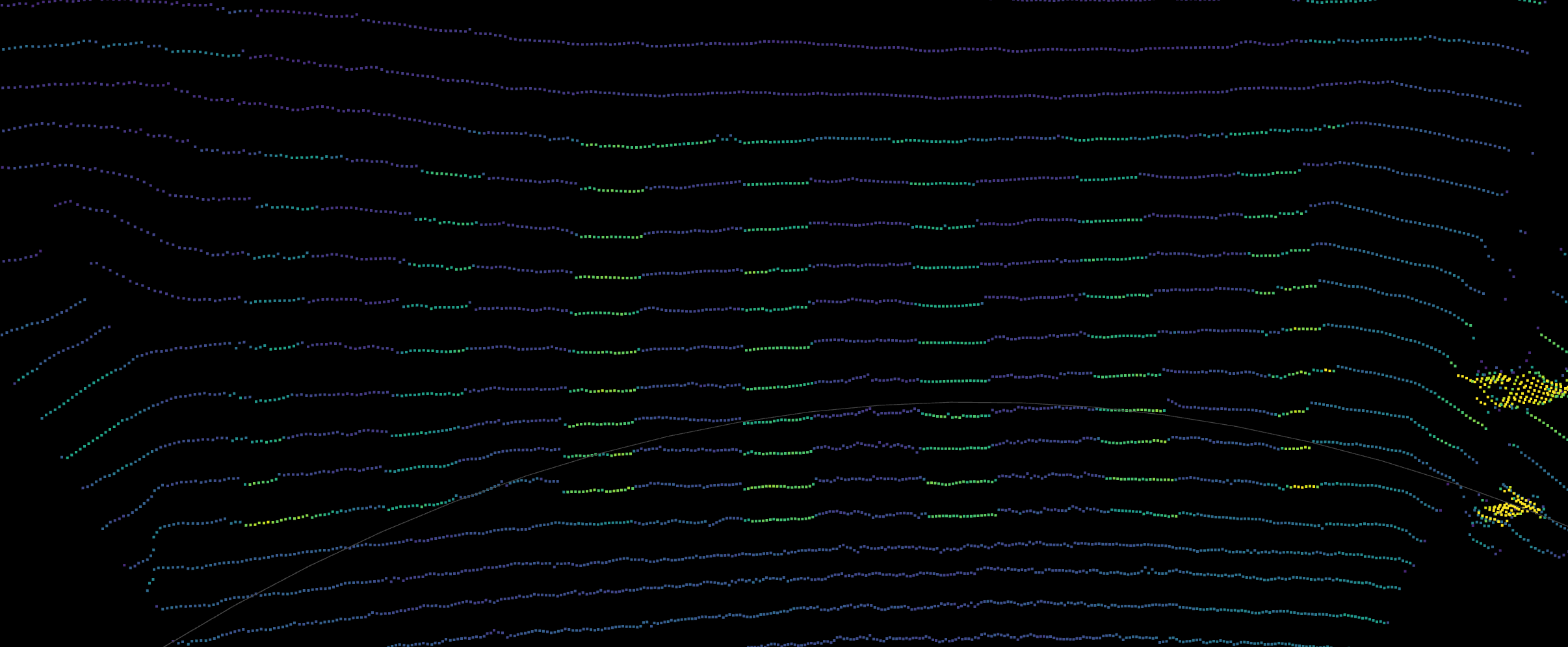
By measuring distance in many directions, an autonomous vehicle can perceive its environment. Each measurement corresponds to a discrete 3D point in space. Through a decade of steady research, engineers designed algorithms capable of leveraging this 3D point cloud to unlock spatial understanding. Obstacle avoidance and precise positioning are just two direct results of this technology.
Distance and bearing measurements can be converted into 3D Cartesian points. For example, given range  and bearing
  ,
,  , the 3D point is:

In contrast, a camera only measures bearing and ambient light intensity. Each pixel of a photo is a measurement of how much light there is in that particular direction. But generally, a camera has much higher bearing resolution than a lidar.

2 Measuring distance
Measuring distance is also known as ranging. Basically, it just measures how close something is. There are in general two ways of doing this:
- Measuring the time somehow, exploiting the fact that light travels at a constant speed (the speed of light)
- Parallax
For measuring the time, there are again two ways:
- Direct time of flight, where we directly measure the time
- Modulated lidar, where we modulate some attribute of the outgoing light, e.g. amplitude, frequency, or polarization
2.1 Direct time of flight pulsed lidar
Direct detection pulsed lidar fires one or more laser pulses. Then, we simply measure the time to see the reflection from the pulse.

where  is the speed of light (
 m/s). The division by 2 is because the range is half of the round trip distance.
Imagine if we have a stopwatch that measures in, say, a nanosecond resolution. If we measure 1000 nanoseconds, then it means the round trip distance was 300 m, which means that the range is 150 m.
This involves measuring the time series data of how much light is seen at any point in time. Since electronics typically run at 1 GHz or so, the time series is discretized on the order of 1 ns, which corresponds to a range of 15 cm. To further improve the ranging accuracy, an interpolation filter is a standard technique in signal processing. Typically ranging accuracy at the centimeter level is possible.
After getting the time series data, the peaks in the series are found, and these correspond to the range.

Usually, it is better to have stronger, shorter pulses. Diode lasers can produce pulses on the order of a couple of nanoseconds, and fiber lasers can produce even shorter pulses with much higher peak energy.
In practice, the laser pulse has some finite duration and shape (rather than being an infinitely short impulse function), so the peak is found in the cross correlation of the outgoing pulse’s shape with the return data, rather than the raw time series data itself. It is possible to send a randomly shaped pulse (or sequence of pulses), and cross correlate the return data against that. This provides much greater resistance against noise, interference, and crosstalk, and is known as a matched filter.
We should note, however, that the shape of the return pulse could be distorted or “smeared out”. This can be due to, for example, hitting a very slanted surface. One strategy to overcome this is to try correlating it with a bunch of different pulse shapes. This technique may be called template matching, dictionary matching, matched filter bank, or model-based detection.
2.1.1 Photodiodes used in pulsed lidar
In order to get a time series of the amount of light per unit time at a super high rate, we need a really fast sensor that can operate at 1 GHz. Usually one of these two types of sensors is used:
- Linear-mode avalanche photodiodes (APD)
- Geiger-mode avalanche photodiodes, also known as single-photon avalanche photodiodes (SPAD)
Other types of sensors such as CCD sensors are not fast enough for this application.
A photodiode is a diode that also has the photoelectric effect.
A diode is like a one-way valve for electricity. Just like a one way valve for water, if you try to force things sufficiently in the opposite direction, it will break down, resulting in a huge gush of water. Likewise, if you apply a strong voltage in the reverse direction, it’s called a reverse bias, and a sufficiently strong voltage will cause a sudden spike in electrical current. This is called avalanche breakdown.
Meanwhile, some metals produce an electric current when shining light on it, in an effect known as the photoelectric effect.
Avalanche photodiodes have a reverse bias, meaning that a voltage is applied in the opposite direction of the one-way valve. If the reverse voltage exceeds a certain amount known as the breakdown voltage, it stops acting like a diode. Suddenly, a large current can flow through the device.
Linear-mode APDs have a reverse bias slightly below the breakdown voltage. Here, the current is linearly related to the voltage, but the gain is very high, so that even changing a small voltage results in a large change in the current. Hence, it is a very sensitive way of measuring light intensity.
Geiger- mode avalanche photodiodes (GMAPDs) or single-photon avalanche diodes (SPADs) have such a strong reverse bias that even getting hit by a single photon can make them break down, resulting in a large current spike. The output of a SPAD can be directly connected to a voltage discriminator so that the spike becomes a digital signal from logic 0 to 1.
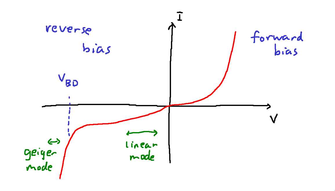
In the above I-V diagram, we see the relationship between the voltage (V) and the current (I).
The breakdown voltage  is labelled.
As you can see, where the linear-mode APD operates, the current is linearly proportional to the voltage.
The Geiger-mode APD operates where the slope is effectively infinitely steep.
is labelled.
As you can see, where the linear-mode APD operates, the current is linearly proportional to the voltage.
The Geiger-mode APD operates where the slope is effectively infinitely steep.
Note on terminology: Typically the word avalanche photodiode (APD) refers to linear-mode APDs. Meanwhile, GMAPDs and SPADs operate in the same way but the term SPAD often refers to silicon devices sensitive to near infrared (850 nm to 940 nm) and GMAPD often refers to InGaAs devices sensitive to longer wavelengths (1064 nm to 1550 nm).
SPADs have the following advantages:
- CMOS compatibility: Silicon SPADs can be made with the complementary metal-oxide-semiconductor (CMOS) process, the same way as computer CPUs and the such. Since they output digital signals, you can fabricate them on the same chip that is used to process the signals. Hence the whole detection pipeline can be made cheaply on a silicon application-specific integrated circuit (ASIC). In contrast, the output of an APD is an analog signal, so a high-speed analog-to-digital converter (ADC) is required. This is very expensive and introduces extra noise. Silicon SPADs also benefit from the immense scaling potentials of the CMOS process, allowing very large arrays to be fabricated at a very fine manufacturing node. Hence, SPADs can be used to make very high resolution, dense arrays, as opposed to APDs which are relatively large and expensive discrete components.
- Higher gain: SPADs have a higher gain than linear mode APDs. In fact, the gain of a SPAD is essentially infinite, allowing it to detect even a single photon.
- Lower temperature dependence: SPADs are less sensitive to temperature than APDs, for which different temperatures can change the sensitivity of the sensor and also affect the dark current.
- Better timing jitter: SPADs output such a sharp spike that you can measure the timing very accurately and reliably.
Meanwhile, APDs have these advantages:
- No dead time and quenching: A linear mode APD essentially continually outputs an analog signal, so there is no need to recharge. In contrast, after a SPAD fires, it takes a while to recharge. During a SPAD avalanche event, it can be destroyed by its own huge current, so the current must be quenched with a resistor to discharge it. After quenching, it needs to recover to its original biasing condition. The reverse bias voltage is typically supplied by a capacitor, which needs to take time to charge back up again. Hence, there is a dead time ranging from around a few nanoseconds (silicon SPADs) to a microsecond (GMAPDs). By avoiding all this, APDs can have simpler circuitry.
- Dynamic range per detector: APDs output a continuous analog output that you can digitize however finely you want, gives better dynamic range per detector (meanwhile a single SPAD has a dynamic range of only 1 bit, it’s either 0 or 1).
- No range walk: Linear mode APDs avoid intensity-dependent range walk and saturation issues, which I discuss in more detail below.
If the return signal from a pulse is very strong, a SPAD array can be saturated at the very beginning of the pulse. If the pulse length is long, ranging may be biased when measuring the range of retroreflective materials. This is also known as range walk.
SPADs are so sensitive that they can be triggered by single photons, but this also makes them sensitive to ambient illumination. Therefore saturation is a concern.
In contrast, the continuous signal from an APD can be digitized with many bits.
To prevent SPADs from being drowned out by ambient light, the probability of detection of any single SPAD must be kept very low. Some techniques include:
- SPADs are usually made really small
- a tight band-pass filter can reject most ambient light
- sometimes an attenuating filter (e.g. a neutral density filter, which attenuates all wavelengths equally) is needed to attenuate the signal even further
2.1.2 SPAD macropixels
Instead of a single SPAD per pixel, several SPADs can be combined into a single “macropixel”. This trade-off results in lower spatial resolution, but the benefit is that it mitigates most of the drawbacks of SPADs.
- Dynamic range increases from 1 bit to as many bits as you have SPADs in the macropixel.
- Dead time of any individual SPAD is mitigated since it is unlikely that all the SPADs will fire at once, meaning that there are always available ones. Of course, in some circumstances (such as retroreflectors) it is still possible for all the SPADs in a macropixel to be saturated.
- SPADs can be made individually smaller, making it unlikely for all of them to fire at once, resulting in better resilience against saturation.
2.1.3 Multi-shot ranging
Even with a macropixel, ranging with SPADs can be noisy as there may only be as many photons measured as there are SPADs in the macropixel. To increase signal strength, the lidar can fire many shots and aggregate the time series data from each shot. This is known as multi-shot ranging.
As an additional bonus, making multiple low-energy shots is somewhat safer than a single high-energy shot as the peak laser energy is less.
The tradeoff is that it takes a longer time to make a measurement, during which you could suffer from motion blur.
2.1.4 Silicon photomultipliers
Silicon photomultipliers are a group of SPADs whose outputs are combined into a single analog signal. This has some advantages:
- Just like the SPAD macropixel, by combining many SPADs, the dead time of any individual SPAD is a less big concern.
- It can be more sensitive than regular linear mode APDs.
- Without the need for digital logic, the chip is simpler and possibly denser than a digital SPAD macropixel.
However, an ADC is still required to digitize the signal.
2.2 Amplitude modulated lidar
Instead of firing pulses, an amplitude modulated lidar continually modulates the laser amplitude at some radio frequency, say, 1 GHz. In other words, it is just a fast blinking light that turns on and off rapidly.
Meanwhile, there are two detectors that turn on and off at the same rate but are out of phase. That is, when detector 1 is on, detector 2 is off, and vice versa.
The range can be estimated by checking the ratio of the light falling in two detectors, for ranges up to a multiple of the modulation wavelength For example, at 1 GHz, the wavelength is 15 cm.
To resolve the range absolutely, the sensor changes the modulation frequency slightly, say, to 1.05 GHz, giving a range estimate modulo a different wavelength. The unknown multiples can then be found as a least common multiple problem.
The advantage of this type of amplitude-modulated lidar is that it is very cheap. There is no need for high-speed timing electronics to count photons at a high speed. Instead, a simple oscillator is sufficient to make the lights and detectors blink at 1 GHz.
Since the detectors just need to measure intensity rather than timing information, they do not need to be very fast, and basic CMOS or CCD sensors will suffice.
This type of lidar is used in RGBD sensors such as the Kinect V2. However, the ranging accuracy is much poorer than needed for automotive purposes, so this type of lidar is not typically used for automotive.
2.3 Frequency modulated lidar
A frequency modulated lidar has a laser that can change in frequency rapidly.
Now, the laser beam goes through a beam splitter, and part of it is sent out, where it hits something, and bounces back. Then, you can combine the part that didn’t go out with the part that bounced back.
When you combine two waves of similar but slightly different frequency, you’ll end up with something called beat. When the waves line up, they will double their strength, and when they are out of phase, they cancel each other out. Then, you can use a photodiode to measure the time series of the combined wave in order to determine the beat frequency, which in turn tells you the range.

Here’s a plot that shows this effect. The main thing is that the beat frequency is proportional to the difference in frequency, so you can measure it relatively easily with a photodiode.

Frequency modulated lidar is known as frequency modulated continuous wave (FMCW) since the laser beam is always on (a continuous wave) that doesn’t turn off. The principle of using the beat to determine the range is known as optical heterodyne detection. Here, “heterodyne” means comparing two slightly different frequencies (as opposed to “homodyne”, where you have the same frequency).
With FMCW lidar, you can also measure the speed of things by measuring the Doppler shift.
The main tradeoff is that you’ll need an expensive fiber laser that can do frequency modulation with highly linear chirps, increasing the overall cost.
2.4 Parallax lidar
A parallax lidar works by triangulation, that is, similar to coincidence rangefinding.
This does not use any timing information at all. A linear photodetector is placed physically offset from the laser. The detector measures the incident angle of the reflected light and obtains the range by triangulation.
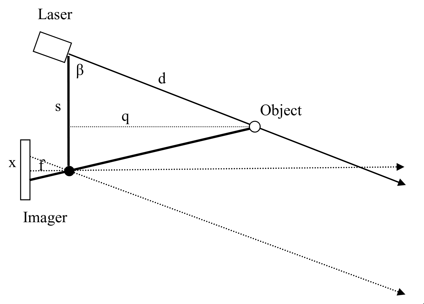
This is rarely or never used in automotive applications but is instead found in robotic vacuum cleaners and other low-speed, low-cost applications. A famous example is the “Low cost laser distance sensor” by Kurt Konolige et al. Many robotic vacuum cleaner sensors are based on this.
A structured light depth camera, also known as active stereo, is a special case of parallax rangefinding. Instead of a single laser beam, it projects a bunch of different dots at once, and instead of a 1D line scan sensor, it has a regular 2D sensor. But the depth measurement is again based on triangulation. Structured light depth cameras are used in the early versions of the Kinect as well as many Intel Realsense cameras.
With parallax rangefinding, it measures disparity, which is the inverse of range, so the uncertainty in range is quite high and grows quadratically with range. As such, it is less suitable for advanced robotics and autonomous cars.
3 Discerning bearing
As mentioned in our introduction, lidar sensors combine distance readings with bearing to produce 3D points. Now that we’ve covered distance, we are ready to discuss how to figure out the directions (bearing) of things.
Lidars can either:
- discern bearing for both tx (the outgoing laser beam) and rx (the detector), or
- discern bearing only for rx but not tx (i.e. a flash lidar), or
- discern bearing only for tx but not rx (for example, some optical phased array lidars only steer the laser beam, but have a “staring” detector that doesn’t distinguish angle).
Discerning bearing is also known as “imaging”. People may describe a system as having both imaged rx and tx, for example.
Generally, having imaged rx and tx is vastly better, since you are only pointing your laser beam where you’re looking, so you get more range and efficiency, and meanwhile the imaged receiver rejects off-angle background light.
There are two main approaches for discerning bearing:
- an array of elements already pointing in different directions
- beam steering, by pointing either your detector or laser in various directions

As with the methods for measuring distance, each method has advantages and disadvantages.
The advantages of arrays are that they don't have any moving parts, each array element can be a lot cheaper, potentially leading to overall cheaper cost, and that it can produce a much greater quantity of points. The advantage of beam steering is that it works with high quality but expensive laser sources such as fiber lasers, the scan pattern may be configurable. Being able to use high quality lasers also unlocks the ability to use ranging modalities unavailable to array-based lidars, such as FMCW.
Note that if you rely on steering very few (even one) lasers, the number of points per second is limited by the speed of light. It takes light a microsecond to travel 300 m round trip, meaning that a single beam lidar is limited to about a million points per second at a range of 150 m. Meanwhile, array-based lidars can easily pump out several million points per second.
3.1 Arrays for discerning bearing
The simplest way to determine direction is to just have an array of elements pointed in various directions.
Basically, you’ll need cheap and small array elements in order to have an array.
| Laser type | Performance | Cost | Array? |
|---|---|---|---|
| VCSEL | Low | Low | Solid state 2D arrays of hundreds of lasers are possible |
| Edge-emitting diodes | Mid | Mid | Discrete 1D arrays of dozens of lasers are typical |
| Fiber | High | High | No, typically used as single laser + beam steering |
| Sensor type | Size | Cost | Array? |
|---|---|---|---|
| SPAD | Small | Low | Solid state 2D arrays of even millions of SPADs are possible |
| APD | Mid | Mid | Discrete 1D arrays of dozens of APDs are typical |
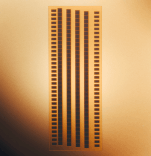
3.1.1 Discrete arrays
With discrete arrays, you have discrete components like edge-emitting laser diodes and avalanche photodiodes that are pointed in different directions. Some early lidars, like the Velodyne VLP 16, literally have 16 circuit boards, each with one laser diode on them, and another 16 circuit boards, each with one APD on them. Then, these 32 circuit boards are glued into place.
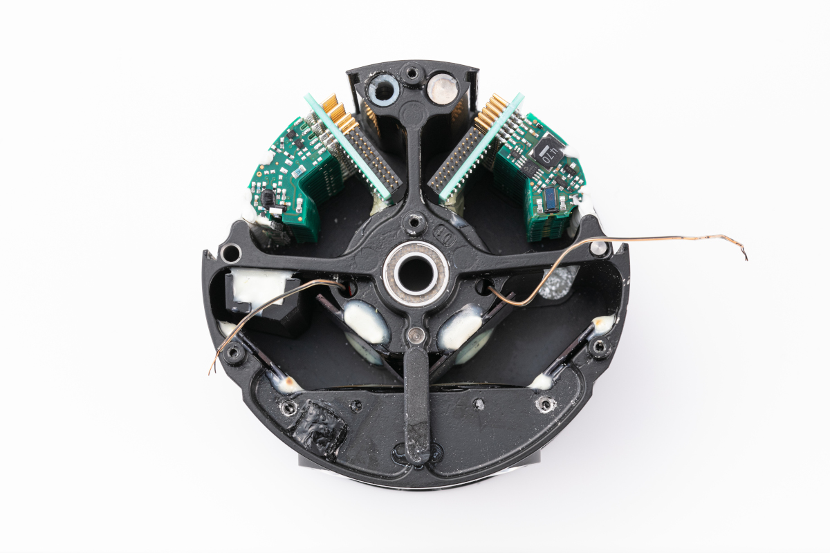
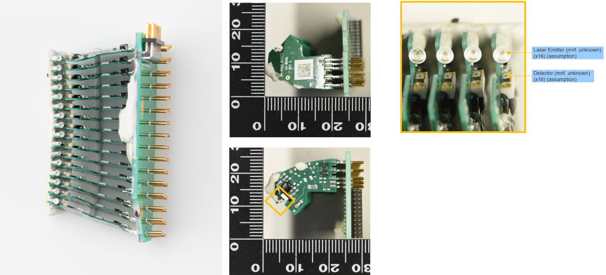
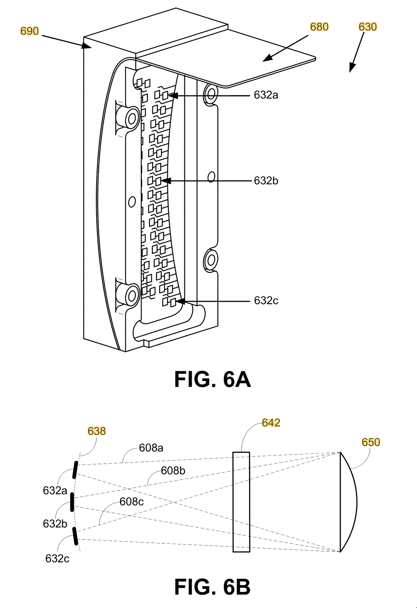
The reason for doing that is because, due to the simple design of the lens, it was necessary to arrange the lasers and detectors along a curved arc. Interestingly, a Google (now Waymo) patent US8836922B1 describes using a flexible substrate to achieve the curve.
3.1.2 Solid state arrays
Solid state arrays put lasers or detectors on a single chip. The obvious benefit is vastly simpler manufacturing and consistency. High performance edge-emitting laser diodes shoot lasers to the sides so you can’t just put a bunch of them in an array on a chip, so you’ll have to make do with lower power VCSELs.
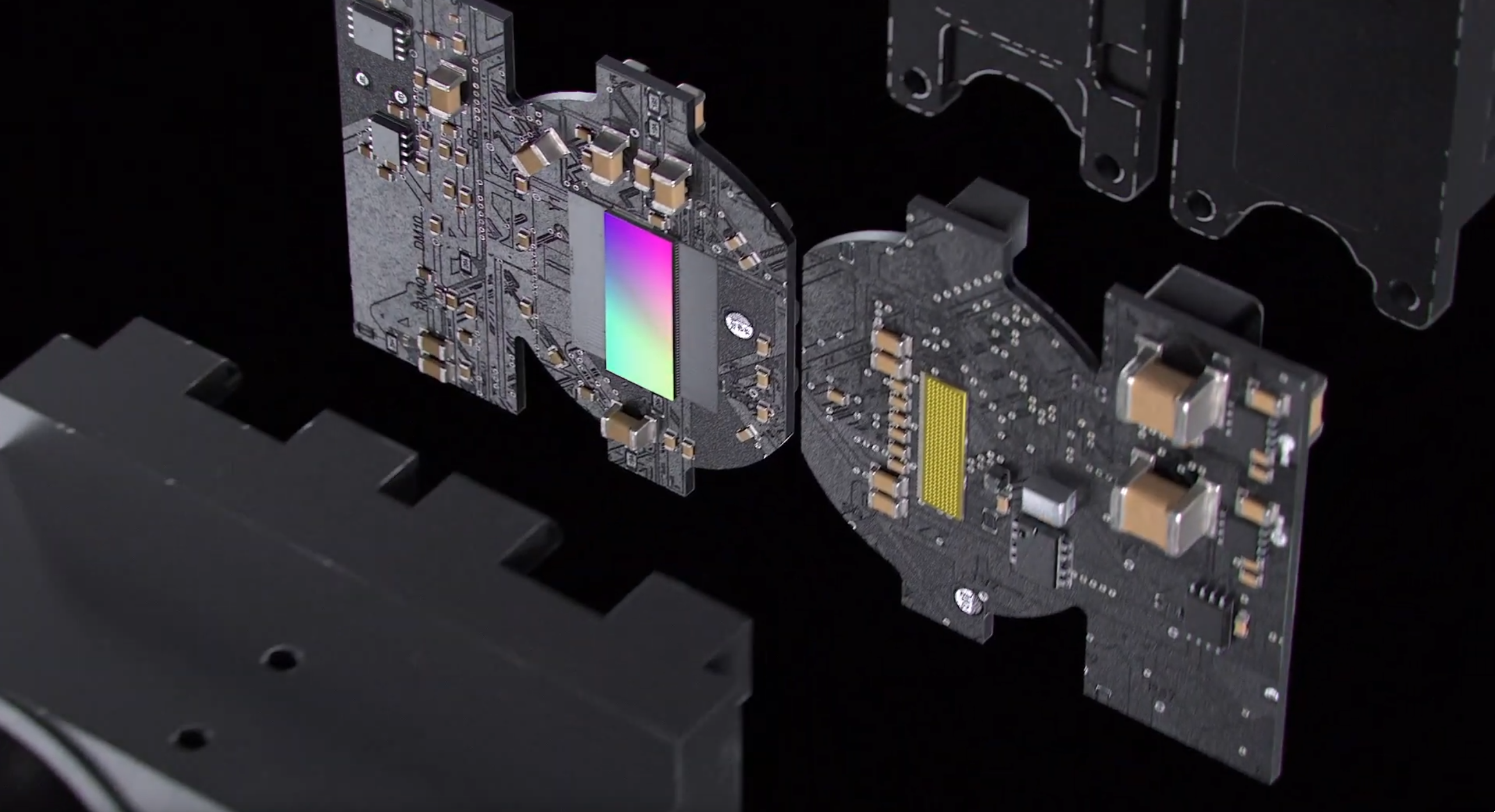
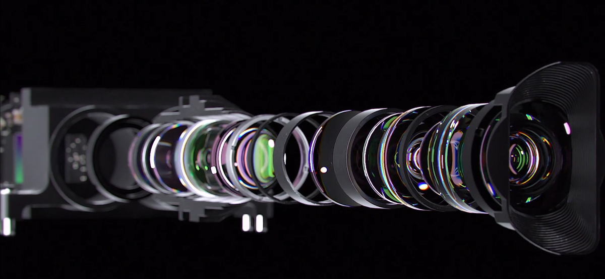
Since the laser array or detector array is now flat, the optical design will be somewhat more complex. You’ll need the lens to be image space telecentric since your flat array of lasers all produces parallel beams.
For lasers, only VCSELs are compatible with this method. As for detectors, SPADs are also vastly more amenable to solid state arrays, although APD arrays are also available (but with fewer elements). This is because, as discussed earlier, SPADs are compatible with typical chipmaking technologies and they output digital signals rather than analog ones, so you can fabricate them on a single chip, whereas APDs would typically require discrete components.
With large arrays, a lidar could sequentially fire small parts of an array instead of all of it at once. This is called electronically scanning. In effect, it is similar to scanning, except there are fixed elements already pointed in different directions rather than the same element being made to point in different directions. Electronically scanning has the advantage of less pixel crosstalk/blooming (more on this later) as well as being able to output more power per beam without running into thermal or safety limits.
3.2 Scanning and beam steering methods
3.2.1 Spinning
Perhaps the most straightforward way to do beam steering is to just spin the whole lidar, which gives you 1D angular discernment. The first advantage is that this gives you 360 degree field of view. This also has the advantage of being highly compatible with arrays, so you can have a vertical array while spinning horizontally. Spinning lidars have basically only one moving part.
An encoder is used to measure the angle of the turret.
The challenges of spinning are that:
- You need to send power and data between the spinning turret and the stationary base somehow. The earliest spinning multi-beam lidar, the Velodyne HDL-64E, used a mercury-wetted slip ring (Mercotac 305). This is very efficient, but expensive, fragile, and somewhat environmentally unfriendly. Later spinning lidars transmit power wirelessly through a transformer, and data wirelessly through an optical link.
- The cylindrical window can degrade optical performance. Some lidars have compensator optics to suppress aberrations from the cylindrical window. The Quanergy M8 had a variant with an octagonal window instead. Some lidars spin externally (such as the Waymo Laser Bear Honeycomb, Velodyne HDL-64E, and Velodyne HDL 32). But spinning externally makes it less robust against the environment.
- Thermal dissipation. The spinning turret houses most of the energy-intensive lasers but it has no direct contact with the outside except through the bearing.
- Despite having only one moving part, the spinning turret is a rather large and heavy part, and some early spinning lidars like Velodynes tended to fail a lot when the bearing was damaged or wore out. This is an especially big problem if the turret isn’t well-balanced.
3.2.2 Spinning mirror
Using a spinning polygonal mirror is one of the oldest and most reliable ways to scan a laser beam, which is again a 1D scanning method. This is used in, for example, laser printers.

As with spinning lidars, an encoder is used to measure the angle of the polygonal mirror.
Compared to spinning the whole turret, this has the main drawback of having a much narrower field of view (about 120 degrees is typical, as opposed to 360 degrees). However, it has the advantage of having a lighter moving part without having to deal with power transmission and heat dissipation and stuff.
3.2.3 Oscillating mirrors/galvos
This is a flat mirror that oscillates in angle to steer the beam, which can be either 1D or 2D.

Typically, a lightweight mirror is connected to a galvanometer in what’s called a mirror galvanometer (galvo). A galvanometer is one of the most basic ways to measure electrical current: it consists of a spring, a magnet, and a solenoid. When a current passes through the solenoid, it creates a magnetic field, which causes a torque to be applied as it tries to align itself with the magnet. The spring resists this force, so the amount it ends up turning is dependent on the current.
Nowadays, fast galvos are incredibly good and are used in all sorts of applications, like laser light shows, engraving, and so on.
Compared to spinning mirrors, this is somewhat less reliable, since reciprocating motion is typically less reliable than constant rotation.
Unlike spinning mirrors, you can have a single mirror that’s actuated in two axes (a 2D galvo) that allows you to steer your beam in both directions with a single mirror.
3.2.4 MEMS mirror
A MEMS (micro-electromechanical system) mirror is simply a mirror that is really small, typically an oscillating mirror. Because it is so small, it is typically considered “solid state” even if it is physically a moving part. Like macroscopic oscillating mirrors, MEMS scanner may be either 1D or 2D.
The primary advantage of MEMS is low cost and relatively better reliability. After all, the rate at which your moving part wears out is strongly dependent on the mass and moments of inertia of that moving part, so keeping it as light as possible makes it more resilient.
There are, however, a couple of drawbacks:
- The optical aperture may be limited by the tiny size of the mirror. With lasers, the bigger the aperture, the more it stays collimated (and hence the less it spreads out), so you want the aperture to be as large as possible usually.
- Cooling a tiny mirror may be hard. Your entire laser output is bouncing off a tiny surface with tiny thermal pathways. Hence, the mirror should be kept as reflective as possible.
3.2.5 Optical phased arrays
A phased array has many array elements whose phase is slightly offset. As the contributions from each element interfere, a beam is formed where they interfere constructively, and everywhere else, destructive interference causes it to cancel out.
Phased arrays are common in radar. However, the fundamental physical problem of phased arrays is that the element size must be close to the size of the wavelength, and the wavelength of light (about a micron) is way smaller than the wavelength of radio waves (ranging from millimeters to many meters). If your array spacing is too big, your beam would have very poor collimation and tons of side lobes.
You can use phased arrays for both the transmitter and receiver. For the receiver, you would have an array of optical antennae which are tiny nanophotonic detectors that can each measure the phase and amplitude.
So far, due to the physical challenges with phased arrays, there have been no commercial successes. The Quanergy S3 and an Israeli startup called Oryx Vision were two well-known entrants to attempt optical antennae.
3.2.6 Baraja SpectrumScan
This uses a frequency sweep laser with a fixed prism. Prisms have dispersion, which means that the index of refraction changes with wavelength (hence turning sunlight into a rainbow), so by changing the wavelength of the laser, the angle is changed. This allows it to scan in 1D. Baraja uses a MEMS mirror for the other axis.
This requires using a high quality fiber laser or tunable diodes that can do large frequency sweeps, which can be costly.
3.2.7 Risley prisms
A prism is a triangular piece of glass that can bend light. Risley prisms are a pair of two prisms that can rotate along the optical axis. When the prisms are lined up, they both bend light the same way, and the beam gets bent a lot. When they are opposite of each other, they cancel each other out, and the beam goes through straight without bending.

Basically, when you have two prisms, one with angle and one with angle  , the
, the  direction of the beam is proportional to:

Speed ratio between prisms: -0.743
The Livox lidars are notable for using Risley prisms. You can make other scan patterns by varying the speed of the prisms, and by putting an array of multiple lasers (e.g. the Livox Horizon’s 6 lasers) instead of one laser.
The advantage of Risley prisms is that, like polygonal mirrors, it’s cheap and robust to have things spinning at a constant speed. However, the disadvantage is very narrow field of view, and a weird scanning pattern. For some applications, the scan pattern can be an advantage, for example surveying applications where the lidar can be stationary for long periods of time, gradually covering a dense area.
3.3 Combining two 1D methods
Many lidars combine two 1D methods, e.g.:
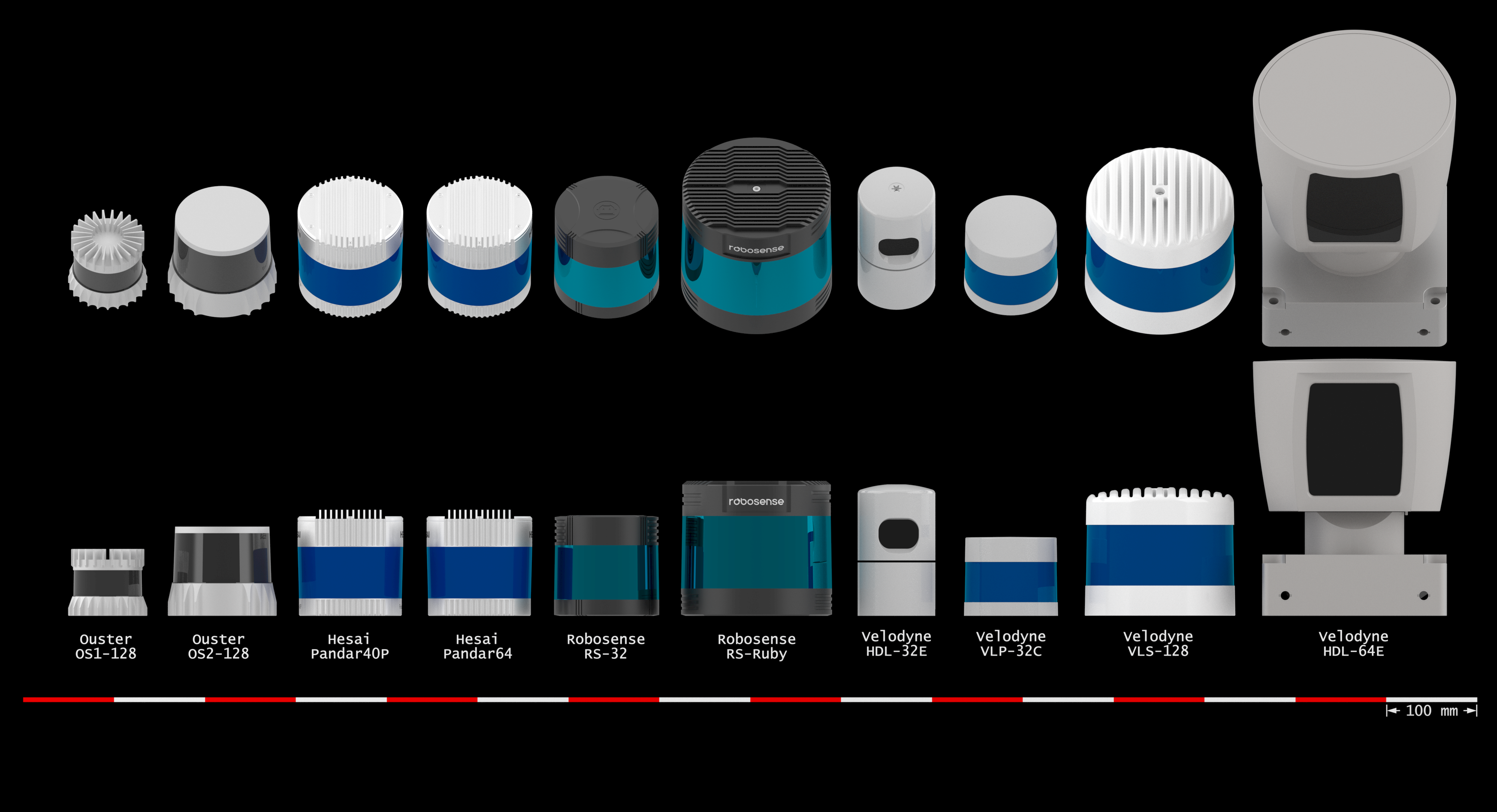
- Horizontally spinning turret + vertical array (e.g. Velodyne pucks, Ouster OS series, Hesai Pandar)
- Horizontally spinning turret + vertically spinning polygonal mirror (e.g. Leica BLK360)
- Horizontal spinning mirror + vertical spinning or oscillating mirror (e.g. Luminar Iris, Seyond Falcon)
- Horizontal spinning mirror + array (e.g. Hesai AT512)
4 Choice of wavelength and eye safety
For lidars, two choices of wavelength are popular:
- near infrared, e.g. 850 nm, 865 nm, 905 nm, 940 nm
- 1550 nm
The main advantage of near IR is that silicon is sensitive in that region, allowing much cheaper, more sensitive silicon detectors, as well as cheap laser sources. In contrast, with 1550 nm, you would need InGaAs semiconductors for your detectors, which are less sensitive and very expensive.
Meanwhile, the main advantage of 1550 nm is that eye safety regulations allow devices to output vastly more power at 1550 nm than in the near IR regime. As a result, 1550 nm lidars tend to have longer range in general.
You can see in the above chart that you are allowed to output hundreds of times more power in the steady state scenario (red curve) at 1550 nm compared to, say, 905 nm. The reason is that the human eyeball focuses near IR light to small spots on the retina, so intense light may damage the retina. On the other hand, 1550 nm light is not focused and is attenuated by water, but at high enough intensities, it will damage the cornea instead.
In practice, manufacturers carefully tune the power of the lasers to be just below the eye safety threshold for both 1550 nm lidars and near IR lidars. That is to say, 1550 nm lidars do in fact output up to 1,000,000 times more pulse energy than 905 nm ones.
Paradoxically, 1550 nm lidars may be more dangerous overall, because of the following reasons:
- If you have many lidars around, the beams from each 905 nm lidar will be focused to a different spot on your retina, and you are no worse off than if there was a single lidar. But if there are many 1550 nm lidars around, their beams will have a cumulative effect at heating up your cornea, potentially exceeding the safety threshold.
- 1550 nm lidars more often rely on beam steering since it is impractical to have an array of expensive fiber lasers. However, if the beam steering were to fail, the laser beam may be fixed in one direction. This can cause laser energy levels thousands of times stronger than the safety threshold in a particular direction, even when the lidar would be under the threshold when it’s scanning properly.
- 1550 nm lidars are known to damage cameras. For example, both AEye lidars and Luminar lidars on the Volvo EX90 are known to destroy cameras. This is an especially worrisome problem with pulsed 1550 nm lidar, but FMCW lidars have a continuous wave with lower peak power and may be slightly safer.
Eye safety aside, 1550 nm is also somewhat more attenuated by both water and water vapor, so they are likely to perform worse in poor weather. In fog, Mie scattering of the water droplets may also impact 1550 nm lidar more, as fog droplets are about 1.5 microns, and the scattering is more as the size of the sphere approaches the wavelength. That said, 1550 nm lidars do have better range to begin with, thanks to outputting a lot more power, so even with attenuation, they are still competitive in rainy situations.
5 Laser sources
There are basically three commonly used types of lasers:
- Vertical cavity surface emitting laser (VCSEL)
- Edge-emitting laser diodes
- Fiber lasers
| Laser type | Typical wavelength(s) | Beam quality (M²) | Coherence / FMCW-ready | Power per element | Cost | Array? |
|---|---|---|---|---|---|---|
| VCSEL | 850–940 nm | Very good, circular | Low–mid linewidth | Low (mW-tens mW) | Low | Excellent: monolithic 2D arrays (10²–10⁵ emitters), fine pitch, easy eye-safety |
| Edge-emitting diodes | 905 nm, 1350-1550 nm | Good (often elliptical) | Mid–high | Mid (100 mW–W class with bars) | Mid | Good: 1D bars/arrays (dozens–hundreds) |
| Fiber/ECDL | 1550 nm | Excellent | High (kHz–100 kHz LW) best for FMCW | High (W class via fiber amps) | High | Poor as dense arrays; usually single source + split/steer |
Vertical cavity surface-emitting lasers (VCSELs) are very cheap and you can make a bunch of them on a chip in a chip-scale solid state array. They are called “vertical cavity” because the beam comes out perpendicular to the chip. You make them by depositing several layers of material on the chip. The main drawback is that they are low peak power.
Edge-emitting laser diodes are a mature technology and are cheap enough to be 1D arrays.
Fiber lasers produce high quality light that is highly coherent. But they are quite expensive so you can probably just afford one or two per lidar. Some lidars split one laser between many lidar heads, as in the case of Baraja’s lidar. Not only are fiber lasers more coherent, they can output millions of times greater power than edge-emitting diode lasers and VCSELs as well as much shorter pulses. Having shorter pulses is very advantageous for pulsed lidar as it improves the range resolution. Some fiber lasers can also vary the wavelength in highly linear chirps, allowing use in FMCW lidars.
The development of these lasers is highly driven by the telecommunications industry where they are used in fiber optics, so the lidar industry sort of profits from that for free.
6 Common lidar problems
6.1 Beam angle calibration
Most spinning + array lidars need a calibrated list of angles, one per beam. Some manufacturers, like Ouster, provide a JSON metadata file containing the elevation and azimuth angles of each of the 128 beams, which is calibrated per lidar. Some manufacturers simply give a nominal set of beam angles for a lidar model that is assumed to be the same for each individual lidar, but in practice, each lidar varies slightly due to manufacturing tolerances. Early Velodynes had very bad beam angles as each of the many circuit boards was individually glued in place and manually aligned.
Here are some ways lidar measurements could have bad beam angles:
- Accidentally forgetting to use the lidar-specific beam angles, or the manufacturer doesn’t provide them
- All the beams are offset by some angle even with lidar-specific beam angles, e.g. bad factory calibration, the lidar got bumped, or due to thermal expansion
This would typically manifest as the ground curving slightly, or the trajectory of the robot curving up or down even when it is expected to be flat.
The well-known KITTI dataset is known to have bad beam angles, and some publications have to manually calibrate them in order to achieve good results. For example, in IMLS-SLAM by J. E. Deschaud:
The drift we get on the KITTI benchmark is not as good as the results we obtained with the Velodyne HDL32. This is due to three facts. First, we found a distortion of the scan point clouds because of a bad intrinsic calibration (we did a calibration of the intrinsic vertical angle of all laser beams of 0.22 degrees using the training data). Second, we found big errors in GPS data (used as ground truth) with, for example, more than 5 m in the beginning of sequence 8.
6.2 Range offsets
Lidars sometimes have different range offsets for each laser. This can happen when using discrete arrays where each laser-detector pair are separate components that need to be individually calibrated.
2011_09_26/2011_09_26_drive_0084_extract/velodyne_points/data/0000000035.txt from the KITTI dataset.
Due to uncalibrated range offsets for some of the lasers of the
Velodyne HDL-64E used, points from certain beams are offset by several
centimeters.6.3 Pixel crosstalk/blooming
Blooming affects many lidars. Think of pointing a camera at the sun. There would be huge lens flare and brightness all around the sun. In effect, the light from the sun is “smeared” out onto neighboring pixels. Likewise, when there’s a strong lidar return, there could be spurious returns next to the shiny object.
With array lidars, neighboring detectors sometimes pick up on the return meant for a different detector. This is called crosstalk. However, even single beam lidars can suffer from blooming just due to the fact that the beam has some divergence and that the optics are imperfect.
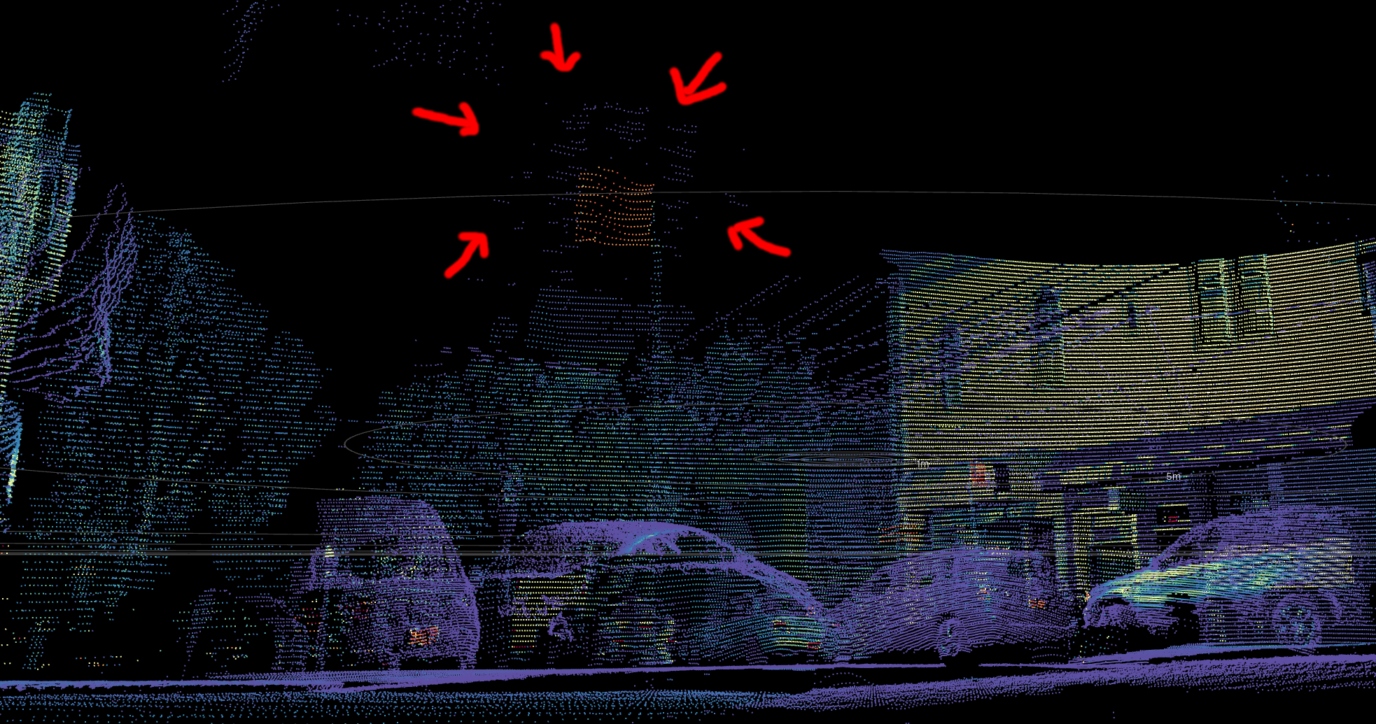
This effect typically can’t be easily calibrated away, and is usually handled in lidar firmware.
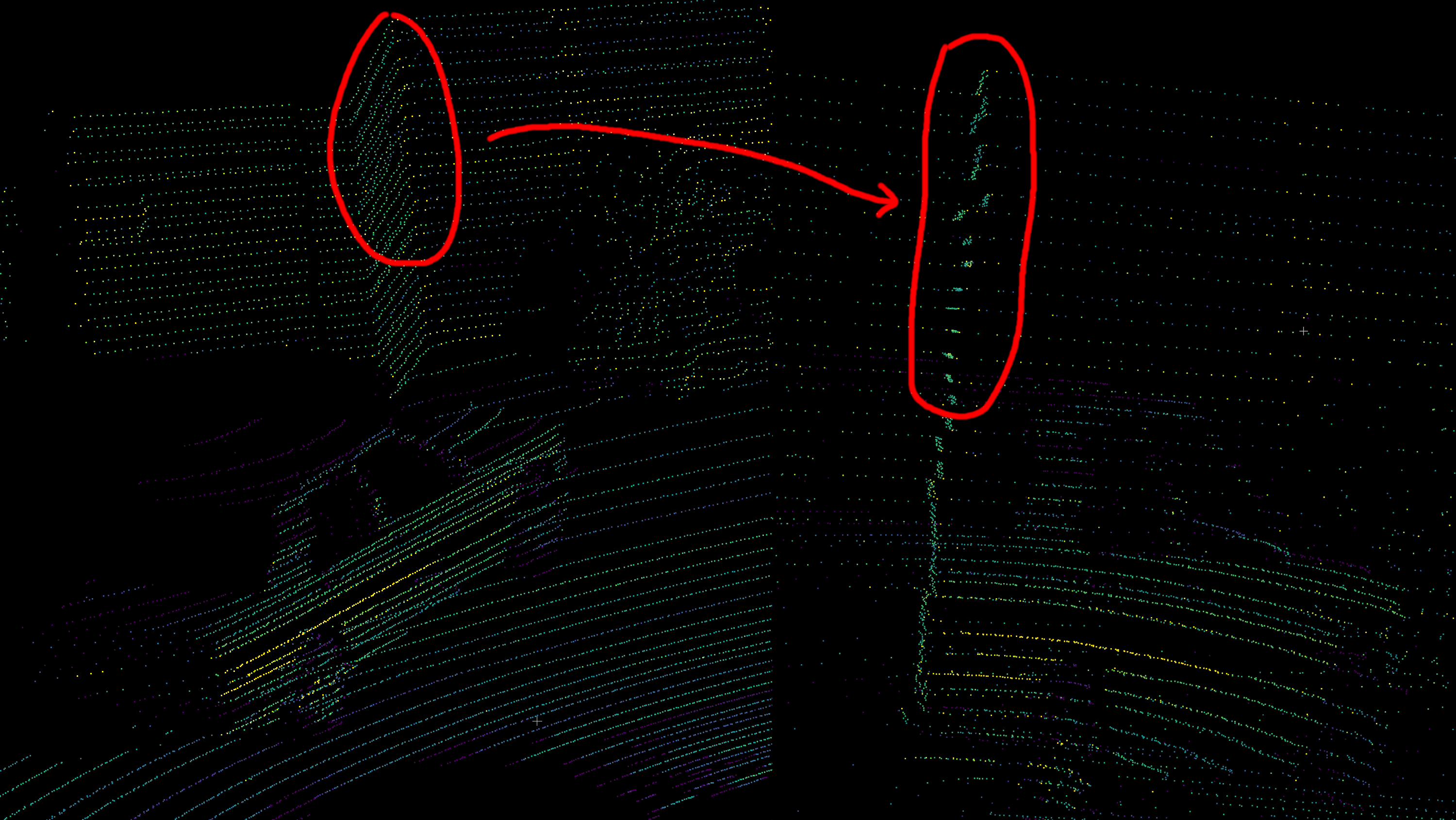
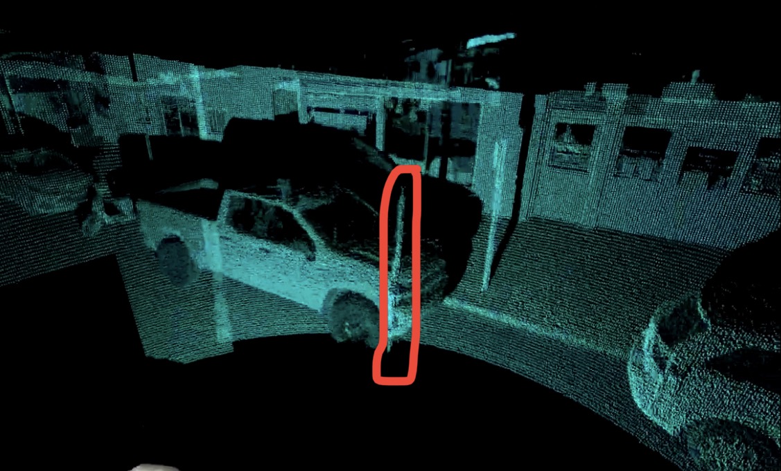
6.4 Intensity-dependent range bias
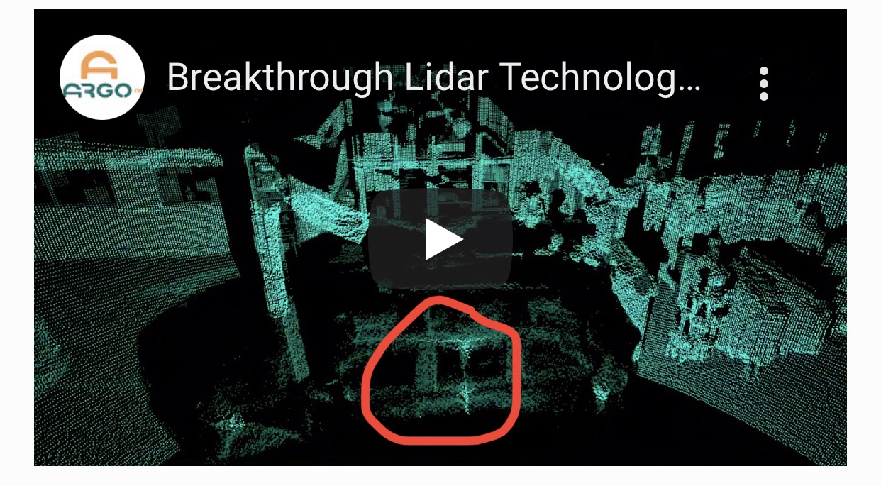
This typically affects SPAD lidars like early Ouster lidars and the now-defunct Argo (formerly Princeton Lightwave) lidar. The reason is that when the return is very strong, all the SPADS get saturated at the beginning of the pulse.
Typically, a pulse is a few nanoseconds long, which means up to a few meters in physical length of the light pulse. Even a slight saturation effect can cause the the peak of the time series to be biased significantly. Very advanced signal processing techniques are needed to compensate for this.
6.5 Encoder hysteresis
Hysteresis in an encoder would typically manifest as some kind of lag, e.g. if it’s rotating clockwise, it could output measurements with slightly different offset than when it’s at the same angle but rotating counter clockwise. Some lidars, such as the Luminar Iris, use encoders for an oscillating beam scanner for vertical beam scanning. It also has a mode where part of the point cloud is an “up-scan” and the other part is a “down-scan”, and the two are superimposed. Often, the point cloud of the up- and down-scans do not align well, even when the vehicle is stationary, suggesting that there may be hysteresis in the encoder.
This may manifest as double-layer point clouds in the ground.
6.6 Encoder physical offset
The encoder used in many spinning lidars is a circular ring with a bunch of ticks engraved on it at regular intervals.
However, it is possible that the encoder is physically offset to the side, because the ring is often just glued in place by humans. This results in a sinusoidal error.


This effect can cause a straight corridor to appear consistently curved to one side.
6.7 Multiple lidars in a box
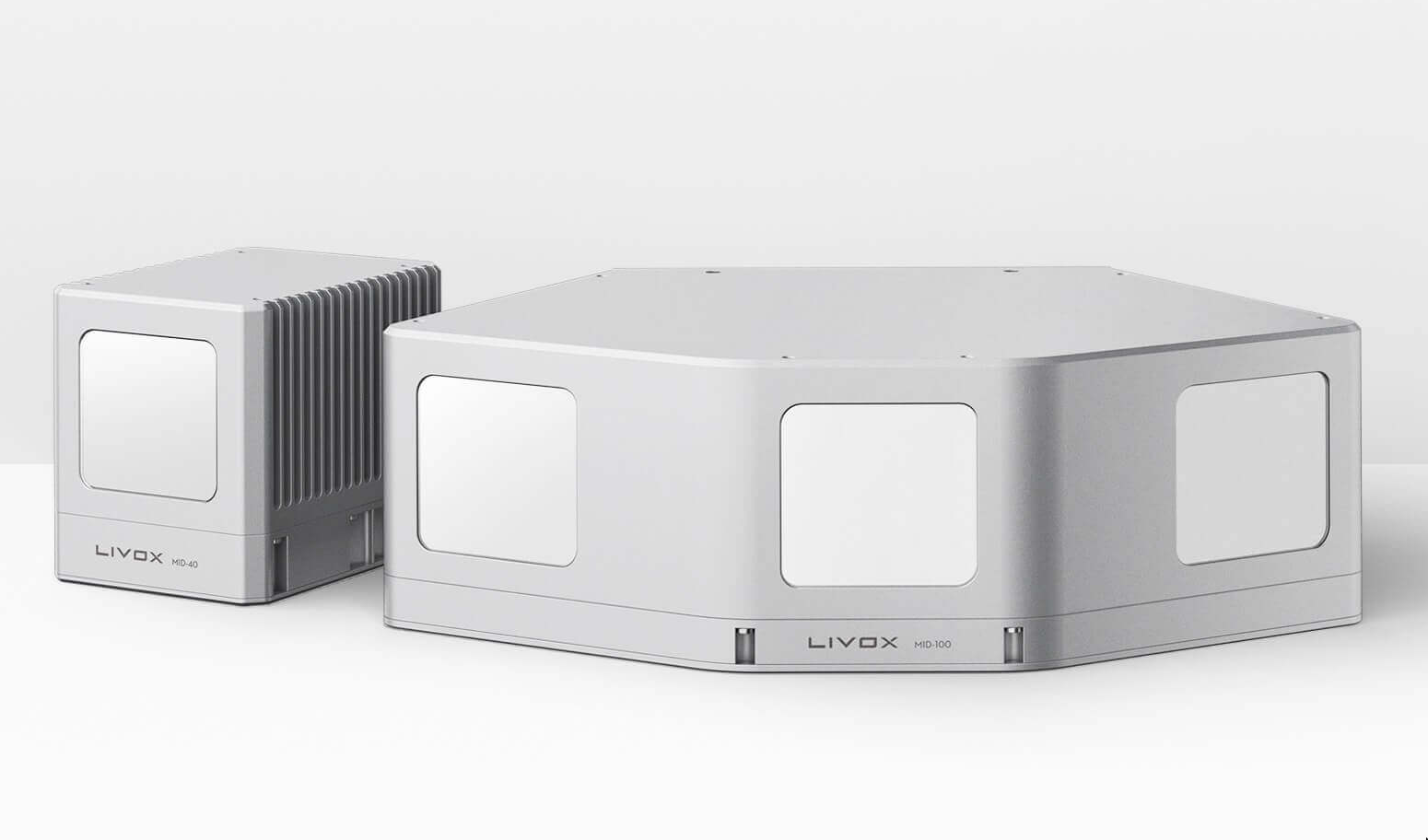
Some lidars are packaged in such a way that there are two or more separate lidars in a box. For example, the Livox Mid 100 comprises three Mid-40s arranged side by side.
Sometimes, physically jostling the lidar can cause the multiple separate lidars to become misaligned. It would then be necessary to treat them as separate lidars and calibrate their orientations accurately.
7 FAQ
7.1 LiDAR vs lidar
Should it be capitalized as “LiDAR” instead of “lidar”?
No! We should use the lowercase because it’s a commonly used word just like radar. When radar was some sort of highly exotic military technology, it made sense to use all caps for the acronym “radio detection and ranging”, but by now it is so common that we should use lowercase. Many other words started out capitalized when new and exotic, but became lowercase once commonplace:
- laser, Light Amplification by Stimulated Emission of Radiation
- scuba, Self-Contained Underwater Breathing Apparatus
- taser, Thomas A. Swift’s Electric Rifle
Now that most phones and some cars are equipped with lidar, it’s a good time to just use lowercase. Perhaps the main barrier to doing so is Apple’s autocorrect.
7.2 Are rectangular lidars solid state?
No, not necessarily. Whether or not something is solid state is based on whether it has macroscopic moving parts in it, not based on its shape.
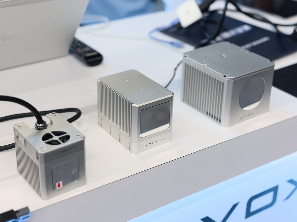
Livox lidars are often mistakenly assumed to be solid state, but they are in fact mechanically scanning with some using Risley prisms and some using mirrors.
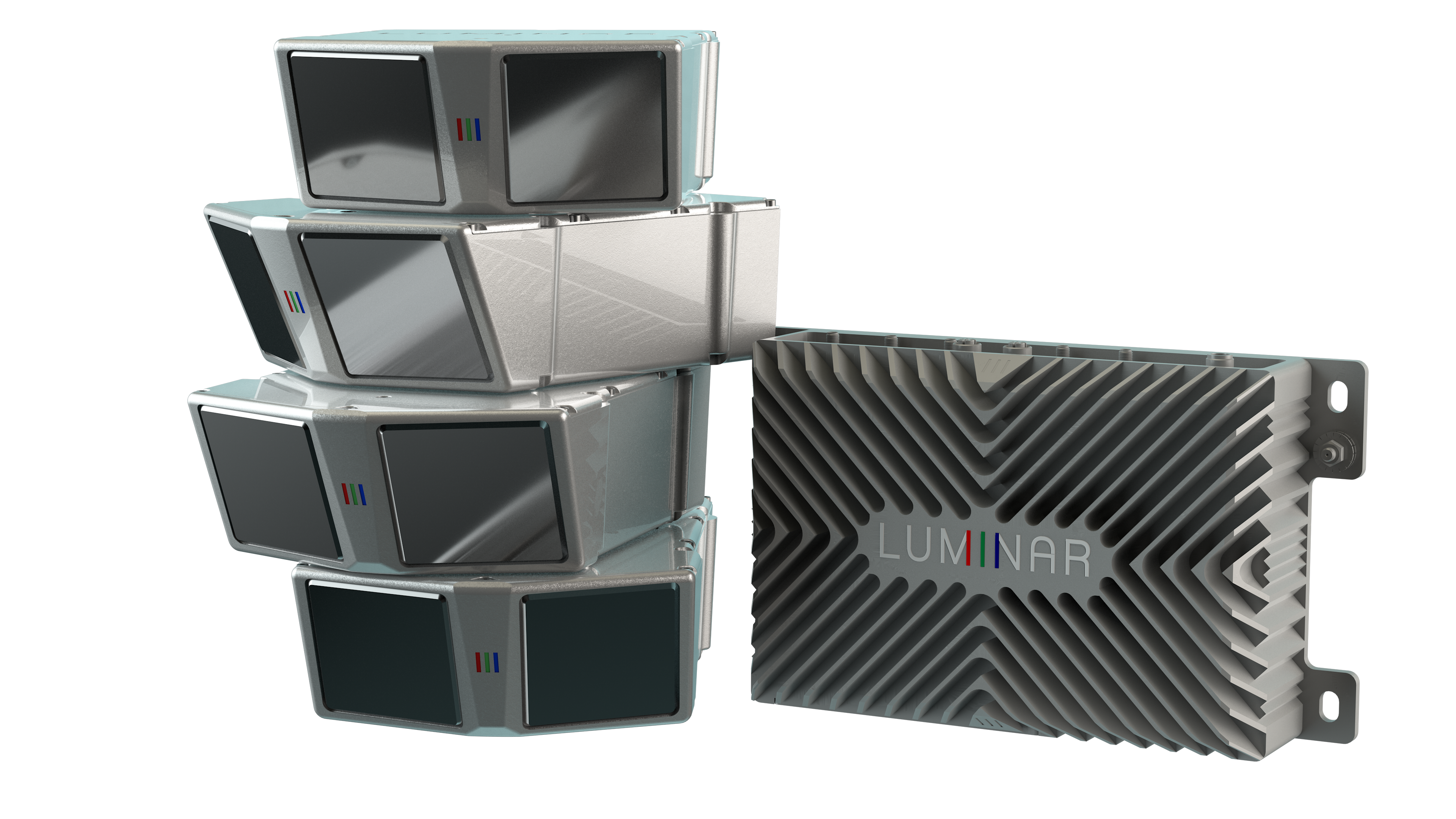
Likewise, Luminar lidars are often assumed to be solid state, but they are not. The Luminar Hydra uses galvos and the Luminar Iris uses polygonal mirrors.
Solid state lidars are often perceived to be more durable and reliable. Lidar manufacturers have taken note of this market bias in customers, and marketed accordingly. For example, the Velodyne HDL-64 was marketed as solid state (even though it is externally spinning) in their 2016 press release announcing the VLP-32A.
Based on his experience during this challenge, Hall recognized the limitations of stereovision and developed the HDL-64 Solid-State Hybrid LiDAR sensor.
As justification, however, one might consider that it has an array of 64 lasers to distinguish vertical bearing, so perhaps it could be called 50% solid state as mechanical scanning is used only for the horizontal direction! In contrast, Luminar and Livox lidars use mechanical scanning for both directions, despite being a single non-spinning box.