Common lidar problems
Beam angle calibration
Most spinning + array lidars need a calibrated list of angles, one per beam. Some manufacturers, like Ouster, provide a JSON metadata file containing the elevation and azimuth angles of each of the 128 beams, which is calibrated per lidar. Some manufacturers simply give a nominal set of beam angles for a lidar model that is assumed to be the same for each individual lidar, but in practice, each lidar varies slightly due to manufacturing tolerances. Early Velodynes had very bad beam angles as each of the many circuit boards was individually glued in place and manually aligned.
Here are some ways lidar measurements could have bad beam angles:
- Accidentally forgetting to use the lidar-specific beam angles, or the manufacturer doesn’t provide them
- All the beams are offset by some angle even with lidar-specific beam angles, e.g. bad factory calibration, the lidar got bumped, or due to thermal expansion
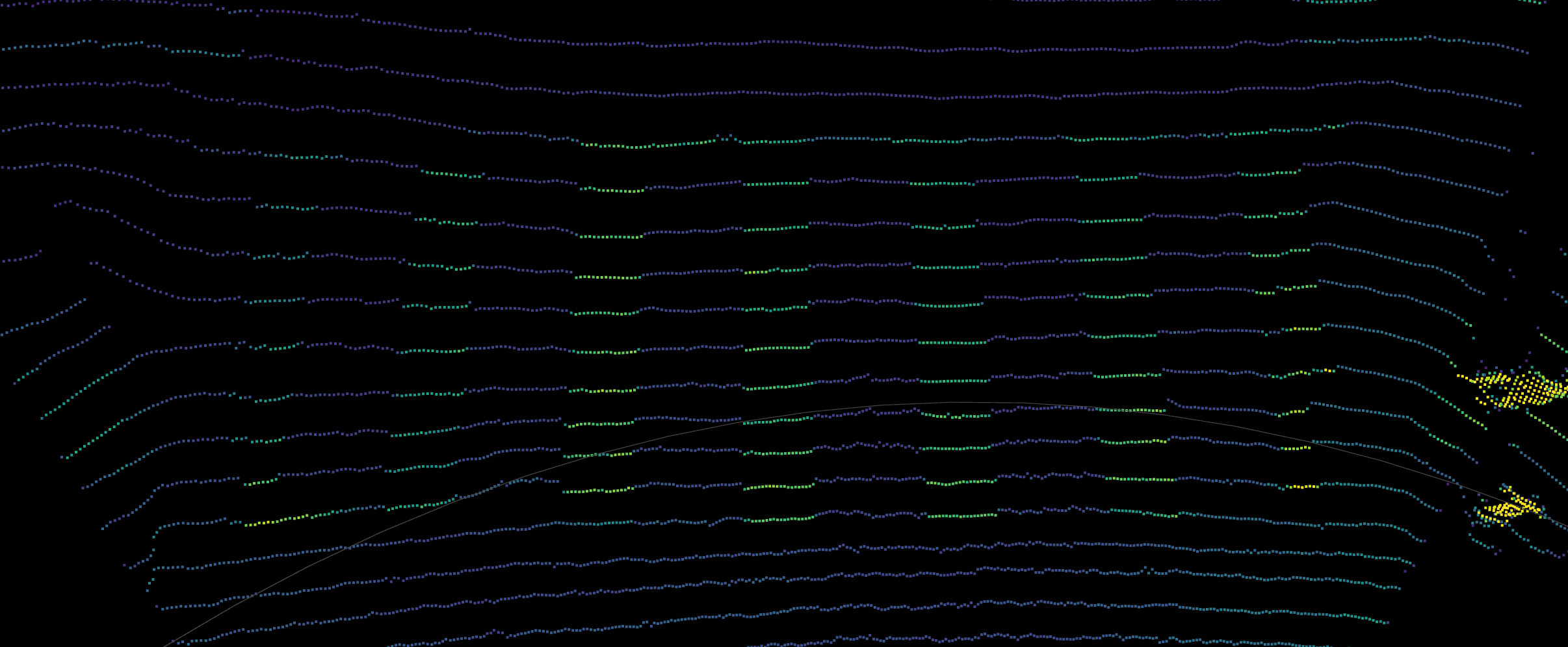
This would typically manifest as the ground curving slightly, or the trajectory of the robot curving up or down even when it is expected to be flat.
The well-known KITTI dataset is known to have bad beam angles, and some publications have to manually calibrate them in order to achieve good results. For example, in IMLS-SLAM by J. E. Deschaud:
The drift we get on the KITTI benchmark is not as good as the results we obtained with the Velodyne HDL32. This is due to three facts. First, we found a distortion of the scan point clouds because of a bad intrinsic calibration (we did a calibration of the intrinsic vertical angle of all laser beams of 0.22 degrees using the training data). Second, we found big errors in GPS data (used as ground truth) with, for example, more than 5 m in the beginning of sequence 8.
Range offsets
Lidars sometimes have different range offsets for each laser. This can happen when using discrete arrays where each laser-detector pair are separate components that need to be individually calibrated.
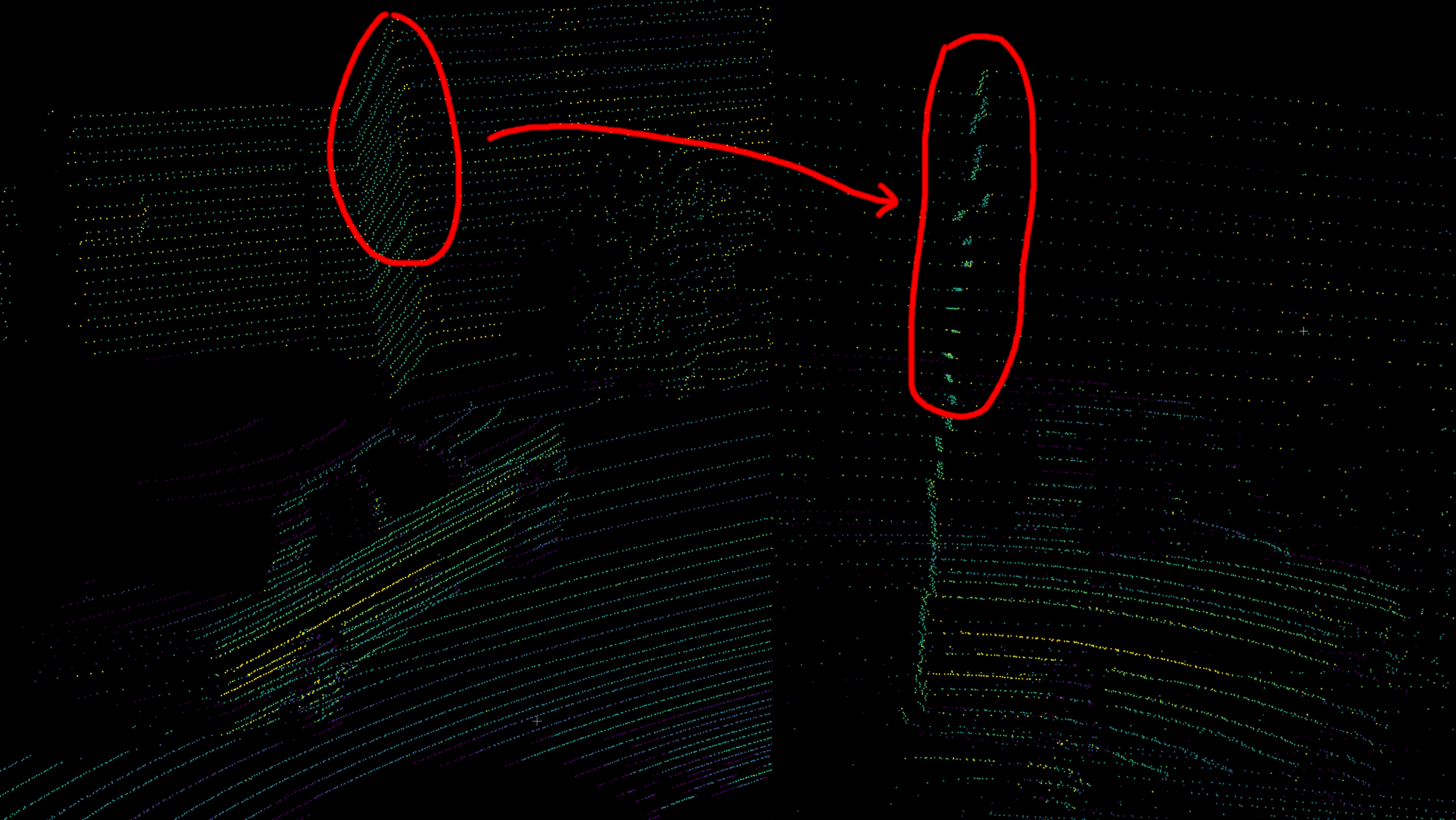
2011_09_26/2011_09_26_drive_0084_extract/velodyne_points/data/0000000035.txt from the KITTI dataset. Due to uncalibrated range offsets for some of the lasers of the Velodyne HDL-64E used, points from certain beams are offset by several centimeters.Pixel crosstalk/blooming
Blooming affects many lidars. Think of pointing a camera at the sun. There would be huge lens flare and brightness all around the sun. In effect, the light from the sun is “smeared” out onto neighboring pixels. Likewise, when there’s a strong lidar return, there could be spurious returns next to the shiny object.
With array lidars, neighboring detectors sometimes pick up on the return meant for a different detector. This is called crosstalk. However, even single beam lidars can suffer from blooming just due to the fact that the beam has some divergence and that the optics are imperfect.
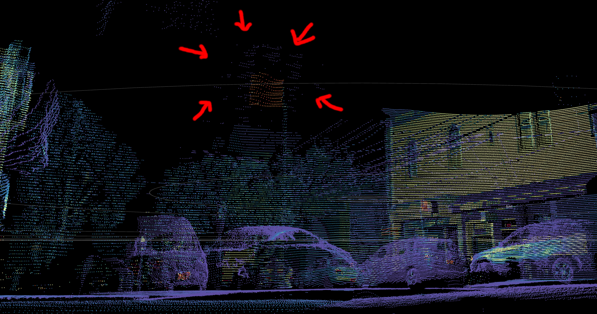
This effect typically can’t be easily calibrated away, and is usually handled in lidar firmware.
Intensity-dependent range bias
This typically affects SPAD lidars like early Ouster lidars and the now-defunct Argo (formerly Princeton Lightwave) lidar. The reason is that when the return is very strong, all the SPADs get saturated at the very beginning of the pulse.
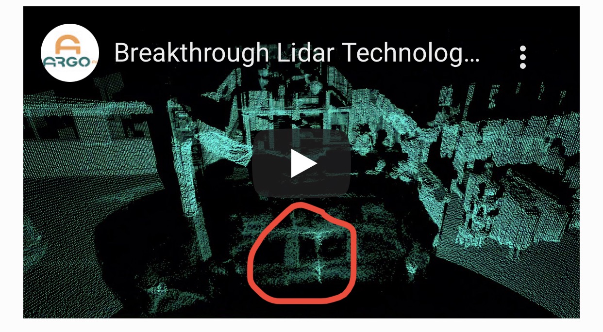
Typically, a pulse is a few nanoseconds long, which means up to a few meters in physical length of the light pulse. Even a slight saturation effect can cause the peak of the time series to be biased significantly. Very advanced signal processing techniques are needed to compensate for this.
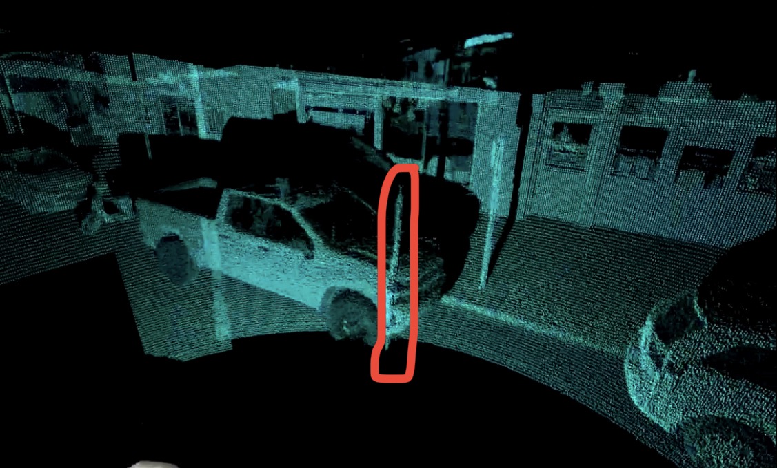
Encoder hysteresis
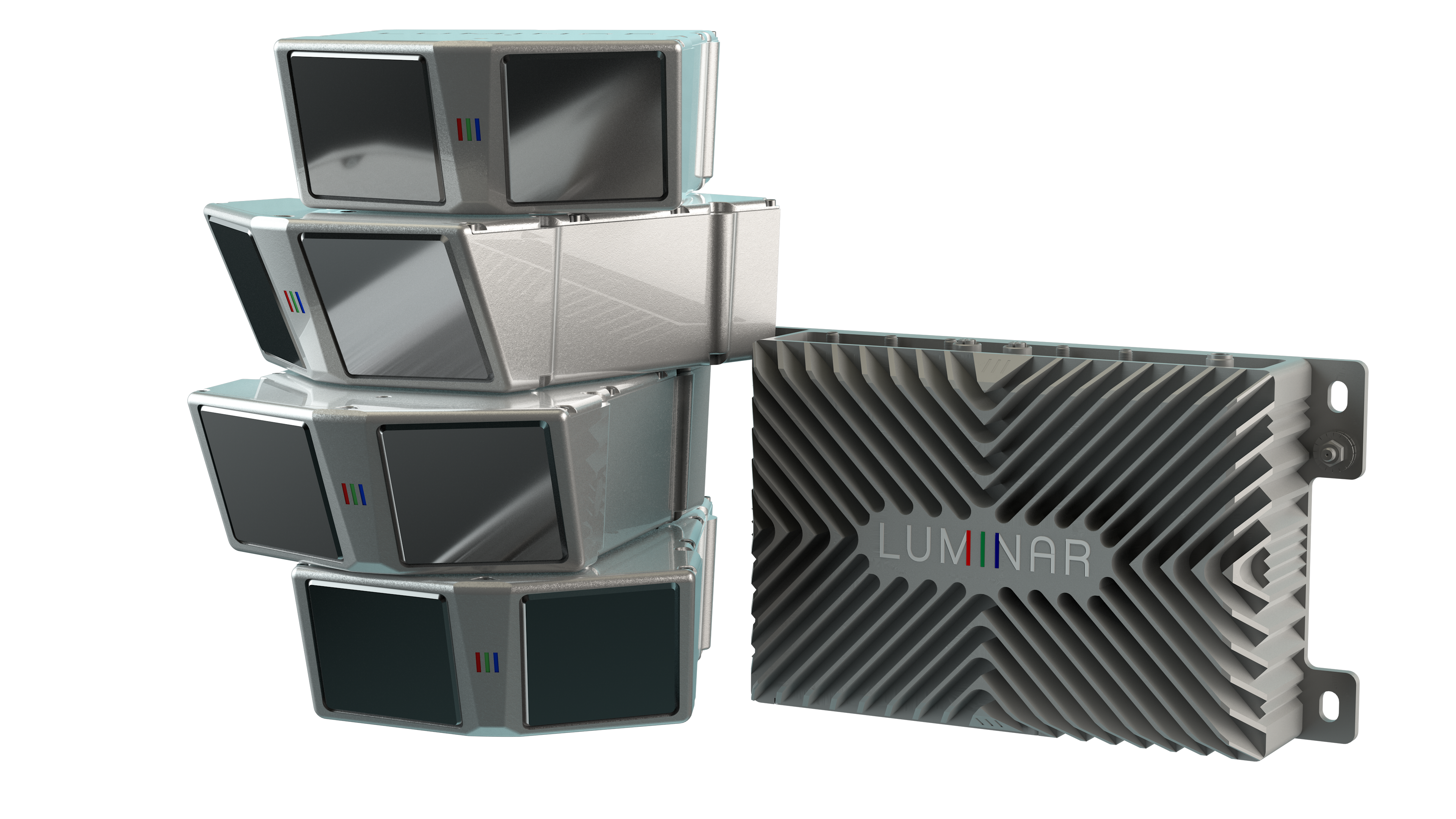
Hysteresis in an encoder would typically manifest as some kind of lag, e.g. if it’s rotating clockwise, it could output measurements with slightly different offset than when it’s at the same angle but rotating counter clockwise. Some lidars, such as the Luminar Iris, use encoders for an oscillating beam scanner for vertical beam scanning. It also has a mode where part of the point cloud is an “up-scan” and the other part is a “down-scan”, and the two are superimposed. Often, the point cloud of the up- and down-scans do not align well, even when the vehicle is stationary, suggesting that there may be hysteresis in the encoder.
This may manifest as double-layer point clouds in the ground.
Encoder physical offset
The encoder used in many spinning lidars is a circular ring with a bunch of ticks engraved on it at regular intervals.
However, it is possible that the encoder is physically offset to the side, because the ring is often just glued in place by humans. This results in a sinusoidal error.


This effect can cause a straight corridor to appear consistently curved to one side.
Multiple lidars in a box
Some lidars are packaged in such a way that there are two or more separate lidars in a box. For example, the Livox Mid 100 comprises three Mid-40s arranged side by side.
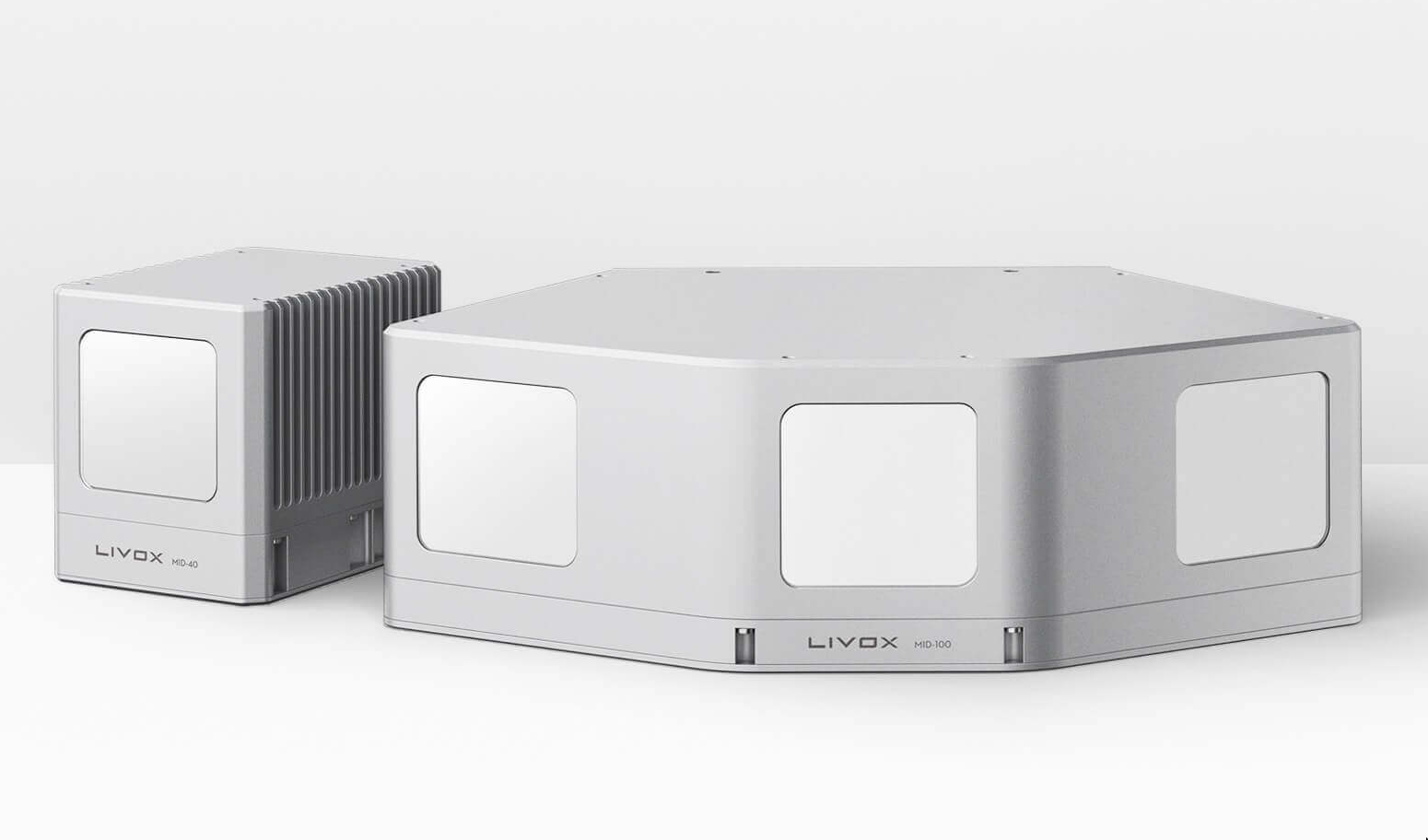
Sometimes, physically jostling the lidar can cause the multiple separate lidars to become misaligned. It would then be necessary to treat them as separate lidars and calibrate their orientations accurately.