Measuring distance
Measuring distance is also known as ranging. There are in general two ways of doing this:
- Measuring the time somehow, exploiting the fact that light travels at a constant speed (the speed of light)
- Parallax
For measuring the time, there are again two ways:
- Direct time of flight, where we directly measure the time
- Modulated lidar, where we modulate some attribute of the outgoing light, e.g. amplitude, frequency, or polarization
Direct time of flight pulsed lidar
Direct detection pulsed lidar fires one or more laser pulses. Then, we simply measure the time to see the reflection from the pulse.

where c is the speed of light (3×10⁸ m/s). The division by 2 is because the range is half of the round trip distance.
Imagine if we have a stopwatch that measures in, say, a nanosecond resolution. If we measure 1000 nanoseconds, then it means the round trip distance was 300 m, which means that the range is 150 m.
This involves measuring the time series data of how much light is seen at any point in time. Since electronics typically run at 1 GHz or so, the time series is discretized on the order of 1 ns, which corresponds to a range of 15 cm. To further improve the ranging accuracy, an interpolation filter is a standard technique in signal processing. Typically ranging accuracy at the centimeter level is possible.
After getting the time series data, the peaks in the series are found, and these correspond to the range.

Usually, it is better to have stronger, shorter pulses. Diode lasers can produce pulses on the order of a couple of nanoseconds, and fiber lasers can produce even shorter pulses with much higher peak energy.
In practice, the laser pulse has some finite duration and shape (rather than being an infinitely short impulse function), so the peak is found in the cross correlation of the outgoing pulse’s shape with the return data, rather than the raw time series data itself. It is possible to send a randomly shaped pulse (or sequence of pulses), and cross correlate the return data against that. This provides much greater resistance against noise, interference, and crosstalk, and is known as a matched filter.
We should note, however, that the shape of the return pulse could be distorted or “smeared out”. This can be due to, for example, hitting a very slanted surface. One strategy to overcome this is to try correlating it with a bunch of different pulse shapes. This technique may be called template matching, dictionary matching, matched filter bank, or model-based detection.
Photodiodes used in pulsed lidar
In order to get a time series of the amount of light per unit time at a super high rate, we need a really fast sensor that can operate at 1 GHz. Usually one of these two types of sensors is used:
- Linear-mode avalanche photodiodes (APD)
- Geiger-mode avalanche photodiodes, also known as single-photon avalanche photodiodes (SPAD)
Other types of sensors such as CCD sensors are not fast enough for this application.
A photodiode is a diode that also has the photoelectric effect.
A diode is like a one-way valve for electricity. Just like a one way valve for water, if you try to force things sufficiently in the opposite direction, it will break down, resulting in a huge gush of water. Likewise, if you apply a strong voltage in the reverse direction, it’s called a reverse bias, and a sufficiently strong voltage will cause a sudden spike in electrical current. This is called avalanche breakdown.
Meanwhile, some metals produce an electric current when shining light on it, in an effect known as the photoelectric effect.
Avalanche photodiodes have a reverse bias, meaning that a voltage is applied in the opposite direction of the one-way valve. If the reverse voltage exceeds a certain amount known as the breakdown voltage, it stops acting like a diode. Suddenly, a large current can flow through the device.
Linear-mode APDs have a reverse bias slightly below the breakdown voltage. Here, the current is linearly related to the voltage, but the gain is very high, so that even changing a small voltage results in a large change in the current. Hence, it is a very sensitive way of measuring light intensity.
Geiger-mode avalanche photodiodes (GMAPDs) or single-photon avalanche diodes (SPADs) have such a strong reverse bias that even getting hit by a single photon can make them break down, resulting in a large current spike. The output of a SPAD can be directly connected to a voltage discriminator so that the spike becomes a digital signal from logic 0 to 1.
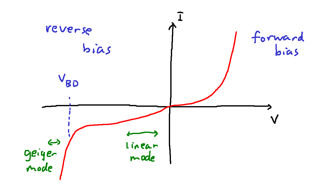
In the above I-V diagram, we see the relationship between the voltage (V) and the current (I). The breakdown voltage VBD is labelled. As you can see, where the linear-mode APD operates, the current is linearly proportional to the voltage. The Geiger-mode APD operates where the slope is effectively infinitely steep.
Note on terminology: Typically the word avalanche photodiode (APD) refers to linear-mode APDs. Meanwhile, GMAPDs and SPADs operate in the same way but the term SPAD often refers to silicon devices sensitive to near infrared (850 nm to 940 nm) and GMAPD often refers to InGaAs devices sensitive to longer wavelengths (1064 nm to 1550 nm).
SPADs have the following advantages:
- CMOS compatibility: Silicon SPADs can be made with the complementary metal-oxide-semiconductor (CMOS) process, the same way as computer CPUs and the such. Since they output digital signals, you can fabricate them on the same chip that is used to process the signals. Hence the whole detection pipeline can be made cheaply on a silicon application-specific integrated circuit (ASIC). In contrast, the output of an APD is an analog signal, so a high-speed analog-to-digital converter (ADC) is required. This is very expensive and introduces extra noise. Silicon SPADs also benefit from the immense scaling potentials of the CMOS process, allowing very large arrays to be fabricated at a very fine manufacturing node. Hence, SPADs can be used to make very high resolution, dense arrays, as opposed to APDs which are relatively large and expensive discrete components.
- Higher gain: SPADs have a higher gain than linear mode APDs. In fact, the gain of a SPAD is essentially infinite, allowing it to detect even a single photon.
- Lower temperature dependence: SPADs are less sensitive to temperature than APDs, for which different temperatures can change the sensitivity of the sensor and also affect the dark current.
- Better timing jitter: SPADs output such a sharp spike that you can measure the timing very accurately and reliably.
Meanwhile, APDs have these advantages:
- No dead time and quenching: A linear mode APD essentially continually outputs an analog signal, so there is no need to recharge. In contrast, after a SPAD fires, it takes a while to recharge. During a SPAD avalanche event, it can be destroyed by its own huge current, so the current must be quenched with a resistor to discharge it. After quenching, it needs to recover to its original biasing condition. The reverse bias voltage is typically supplied by a capacitor, which needs to take time to charge back up again. Hence, there is a dead time ranging from around a few nanoseconds (silicon SPADs) to a microsecond (GMAPDs). By avoiding all this, APDs can have simpler circuitry.
- Dynamic range per detector: APDs output a continuous analog output that you can digitize however finely you want, gives better dynamic range per detector (meanwhile a single SPAD has a dynamic range of only 1 bit, it’s either 0 or 1).
- No range walk: Linear mode APDs avoid intensity-dependent range walk and saturation issues, which I discuss in more detail below.
If the return signal from a pulse is very strong, a SPAD array can be saturated at the very beginning of the pulse. If the pulse length is long, ranging may be biased when measuring the range of retroreflective materials. This is also known as range walk.
SPADs are so sensitive that they can be triggered by single photons, but this also makes them sensitive to ambient illumination. Therefore saturation is a concern.
In contrast, the continuous signal from an APD can be digitized with many bits.
To prevent SPADs from being drowned out by ambient light, the probability of detection of any single SPAD must be kept very low. Some techniques include:
- SPADs are usually made really small
- a tight band-pass filter can reject most ambient light
- sometimes an attenuating filter (e.g. a neutral density filter, which attenuates all wavelengths equally) is needed to attenuate the signal even further
SPAD macropixels
Instead of a single SPAD per pixel, several SPADs can be combined into a single “macropixel”. This trade-off results in lower spatial resolution, but the benefit is that it mitigates most of the drawbacks of SPADs.
- Dynamic range increases from 1 bit to as many bits as you have SPADs in the macropixel.
- Dead time of any individual SPAD is mitigated since it is unlikely that all the SPADs will fire at once, meaning that there are always available ones. Of course, in some circumstances (such as retroreflectors) it is still possible for all the SPADs in a macropixel to be saturated.
- SPADs can be made individually smaller, making it unlikely for all of them to fire at once, resulting in better resilience against saturation.
Multi-shot ranging
Even with a macropixel, ranging with SPADs can be noisy as there may only be as many photons measured as there are SPADs in the macropixel. To increase signal strength, the lidar can fire many shots and aggregate the time series data from each shot. This is known as multi-shot ranging.
As an additional bonus, making multiple low-energy shots is somewhat safer than a single high-energy shot as the peak laser energy is less.
The tradeoff is that it takes a longer time to make a measurement, during which you could suffer from motion blur.
Silicon photomultipliers
Silicon photomultipliers are a group of SPADs whose outputs are combined into a single analog signal. This has some advantages:
- Just like the SPAD macropixel, by combining many SPADs, the dead time of any individual SPAD is a less big concern.
- It can be more sensitive than regular linear mode APDs.
- Without the need for digital logic, the chip is simpler and possibly denser than a digital SPAD macropixel.
However, an ADC is still required to digitize the signal.
Amplitude modulated lidar
Instead of firing pulses, an amplitude modulated lidar continually modulates the laser amplitude at some radio frequency, say, 1 GHz. In other words, it is just a fast blinking light that turns on and off rapidly.
Meanwhile, there are two detectors that turn on and off at the same rate but are out of phase. That is, when detector 1 is on, detector 2 is off, and vice versa.
The range can be estimated by checking the ratio of the light falling in two detectors, for ranges up to a multiple of the modulation wavelength. For example, at 1 GHz, the wavelength is 15 cm.
To resolve the range absolutely, the sensor changes the modulation frequency slightly, say, to 1.05 GHz, giving a range estimate modulo a different wavelength. The unknown multiples can then be found as a least common multiple problem.
The advantage of this type of amplitude-modulated lidar is that it is very cheap. There is no need for high-speed timing electronics to count photons at a high speed. Instead, a simple oscillator is sufficient to make the lights and detectors blink at 1 GHz.
Since the detectors just need to measure intensity rather than timing information, they do not need to be very fast, and basic CMOS or CCD sensors will suffice.
This type of lidar is used in RGBD sensors such as the Kinect V2. However, the ranging accuracy is much poorer than needed for automotive purposes, so this type of lidar is not typically used for automotive.
Frequency modulated lidar
A frequency modulated lidar has a laser that can change in frequency rapidly.
Now, the laser beam goes through a beam splitter, and part of it is sent out, where it hits something, and bounces back. Then, you can combine the part that didn’t go out with the part that bounced back.
When you combine two waves of similar but slightly different frequency, you’ll end up with something called beat. When the waves line up, they will double their strength, and when they are out of phase, they cancel each other out. Then, you can use a photodiode to measure the time series of the combined wave in order to determine the beat frequency, which in turn tells you the range.

Here’s a plot that shows this effect. The main thing is that the beat frequency is proportional to the difference in frequency, so you can measure it relatively easily with a photodiode.

Frequency modulated lidar is known as frequency modulated continuous wave (FMCW) since the laser beam is always on (a continuous wave) that doesn’t turn off. The principle of using the beat to determine the range is known as optical heterodyne detection. Here, “heterodyne” means comparing two slightly different frequencies (as opposed to “homodyne”, where you have the same frequency).
With FMCW lidar, you can also measure the speed of things by measuring the Doppler shift.
The main tradeoff is that you’ll need an expensive fiber laser that can do frequency modulation with highly linear chirps, increasing the overall cost.
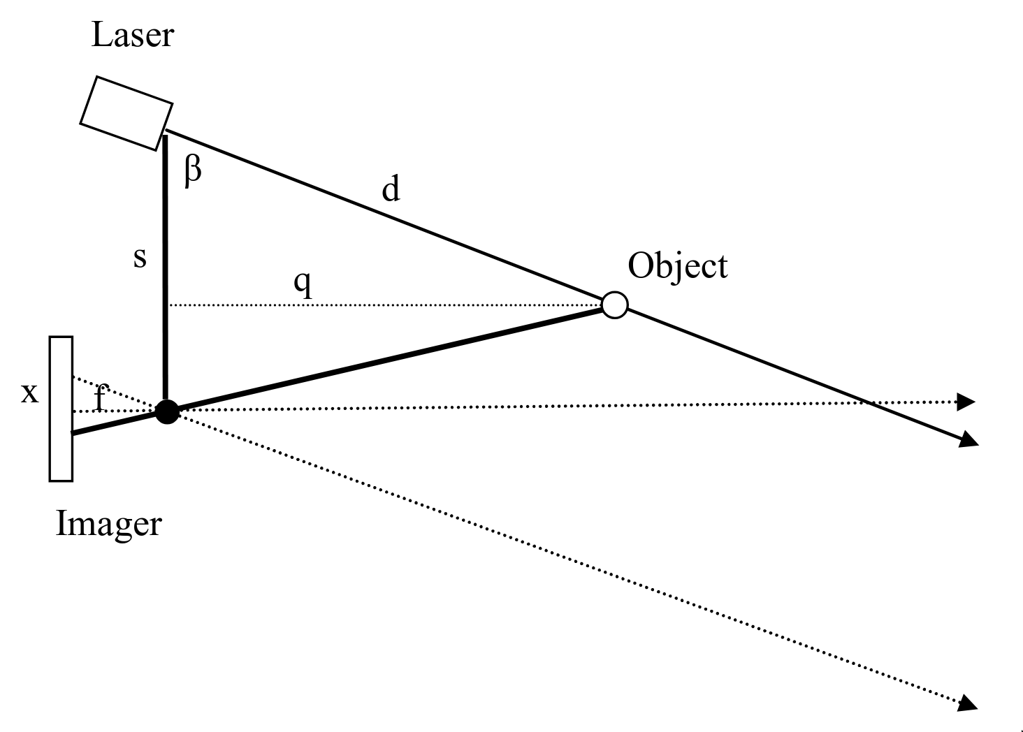
Parallax lidar
A parallax lidar works by triangulation, that is, similar to coincidence rangefinding.
This does not use any timing information at all. A linear photodetector is placed physically offset from the laser. The detector measures the incident angle of the reflected light and obtains the range by triangulation.
This is rarely or never used in automotive applications but is instead found in robotic vacuum cleaners and other low-speed, low-cost applications. A famous example is the “Low cost laser distance sensor” by Kurt Konolige et al. Many robotic vacuum cleaner sensors are based on this.
A structured light depth camera, also known as active stereo, is a special case of parallax rangefinding. Instead of a single laser beam, it projects a bunch of different dots at once, and instead of a 1D line scan sensor, it has a regular 2D sensor. But the depth measurement is again based on triangulation. Structured light depth cameras are used in the early versions of the Kinect as well as many Intel Realsense cameras.
With parallax rangefinding, it measures disparity, which is the inverse of range, so the uncertainty in range is quite high and grows quadratically with range. As such, it is less suitable for advanced robotics and autonomous cars.