Discerning bearing
As mentioned in the introduction, lidar sensors combine distance readings with bearing to produce 3D points. Now that we’ve covered distance, we are ready to discuss how to figure out the directions (bearing) of things.
Lidars can either:
- discern bearing for both tx (the outgoing laser beam) and rx (the detector), or
- discern bearing only for rx but not tx (i.e. a flash lidar), or
- discern bearing only for tx but not rx (for example, some optical phased array lidars only steer the laser beam, but have a “staring” detector that doesn’t distinguish angle).
Discerning bearing is also known as “imaging”. People may describe a system as having both imaged rx and tx, for example.
Generally, having imaged rx and tx is vastly better, since you are only pointing your laser beam where you’re looking, so you get more range and efficiency, and meanwhile the imaged receiver rejects off-angle background light.
There are two main approaches for discerning bearing:
- an array of elements already pointing in different directions
- beam steering, by pointing either your detector or laser in various directions

As with the methods for measuring distance, each method has advantages and disadvantages.
The advantages of arrays are that they don’t have any moving parts, each array element can be a lot cheaper, potentially leading to overall cheaper cost, and that it can produce a much greater quantity of points. The advantage of beam steering is that it works with high quality but expensive laser sources such as fiber lasers, the scan pattern may be configurable. Being able to use high quality lasers also unlocks the ability to use ranging modalities unavailable to array-based lidars, such as FMCW.
Note that if you rely on steering very few (even one) lasers, the number of points per second is limited by the speed of light. It takes light a microsecond to travel 300 m round trip, meaning that a single beam lidar is limited to about a million points per second at a range of 150 m. Meanwhile, array-based lidars can easily pump out several million points per second.
Arrays for discerning bearing
The simplest way to determine direction is to just have an array of elements pointed in various directions.
Basically, you’ll need cheap and small array elements in order to have an array.
| Laser type | Performance | Cost | Array? |
|---|---|---|---|
| VCSEL | Low | Low | Solid state 2D arrays of hundreds of lasers are possible |
| Edge-emitting diodes | Mid | Mid | Discrete 1D arrays of dozens of lasers are typical |
| Fiber | High | High | No, typically used as single laser + beam steering |
Table 1 — Comparison of lasers
| Sensor type | Size | Cost | Array? |
|---|---|---|---|
| SPAD | Small | Low | Solid state 2D arrays of even millions of SPADs are possible |
| APD | Mid | Mid | Discrete 1D arrays of dozens of APDs are typical |
Table 2 — Comparison of receivers
Discrete arrays
With discrete arrays, you have discrete components like edge-emitting laser diodes and avalanche photodiodes that are pointed in different directions. Some early lidars, like the Velodyne VLP 16, literally have 16 circuit boards, each with one laser diode on them, and another 16 circuit boards, each with one APD on them. Then, these 32 circuit boards are glued into place.
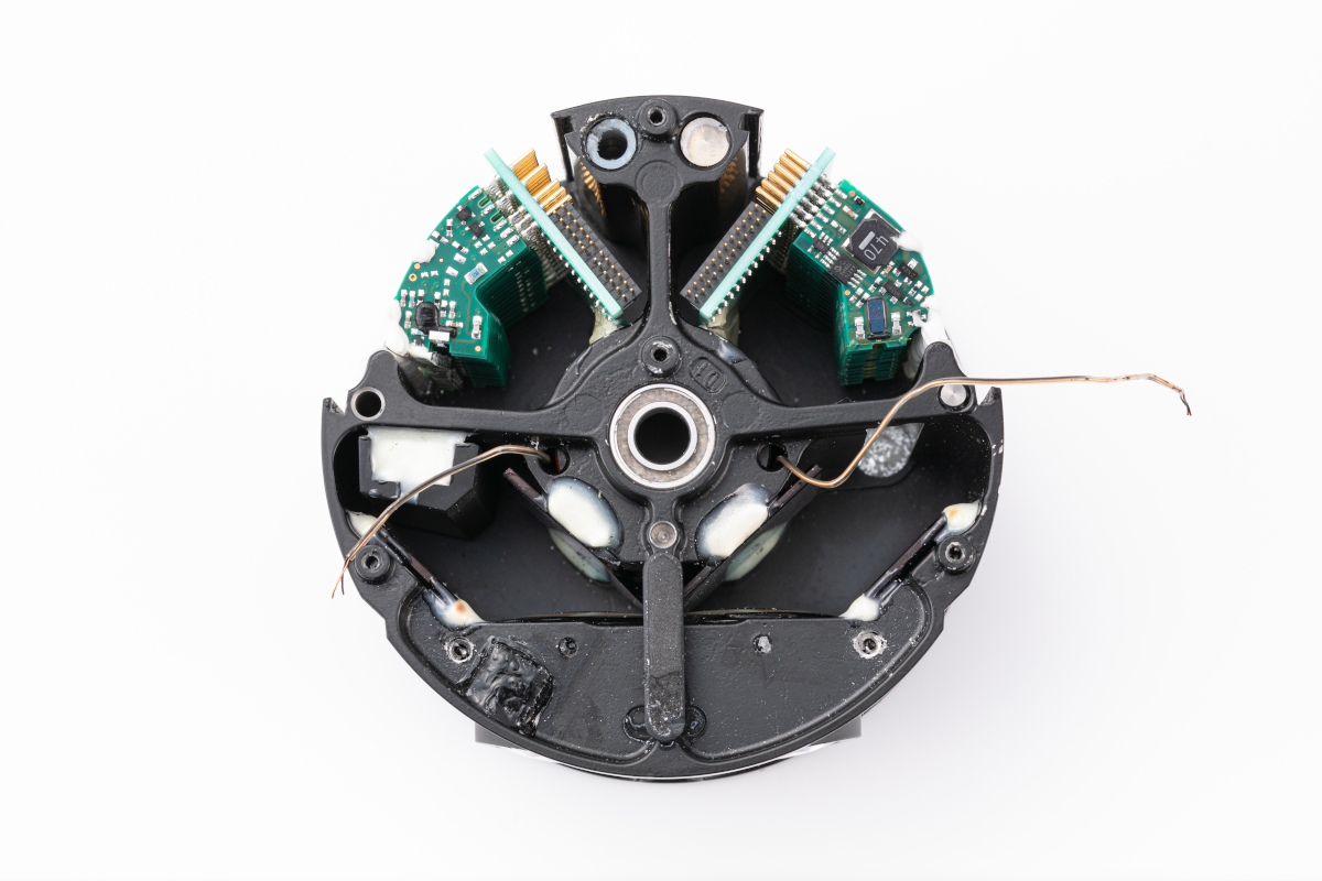
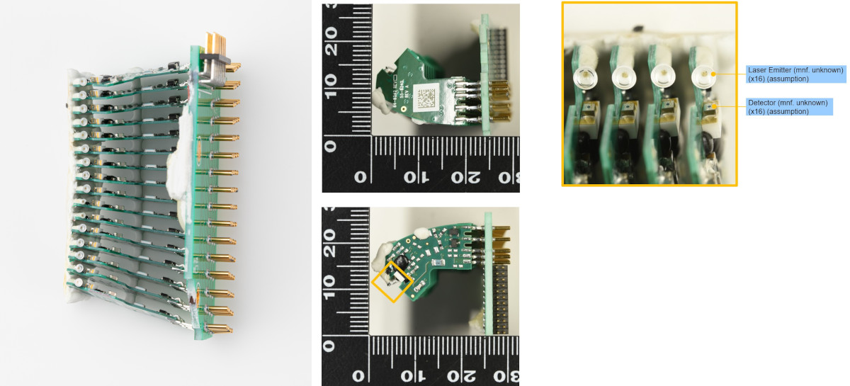
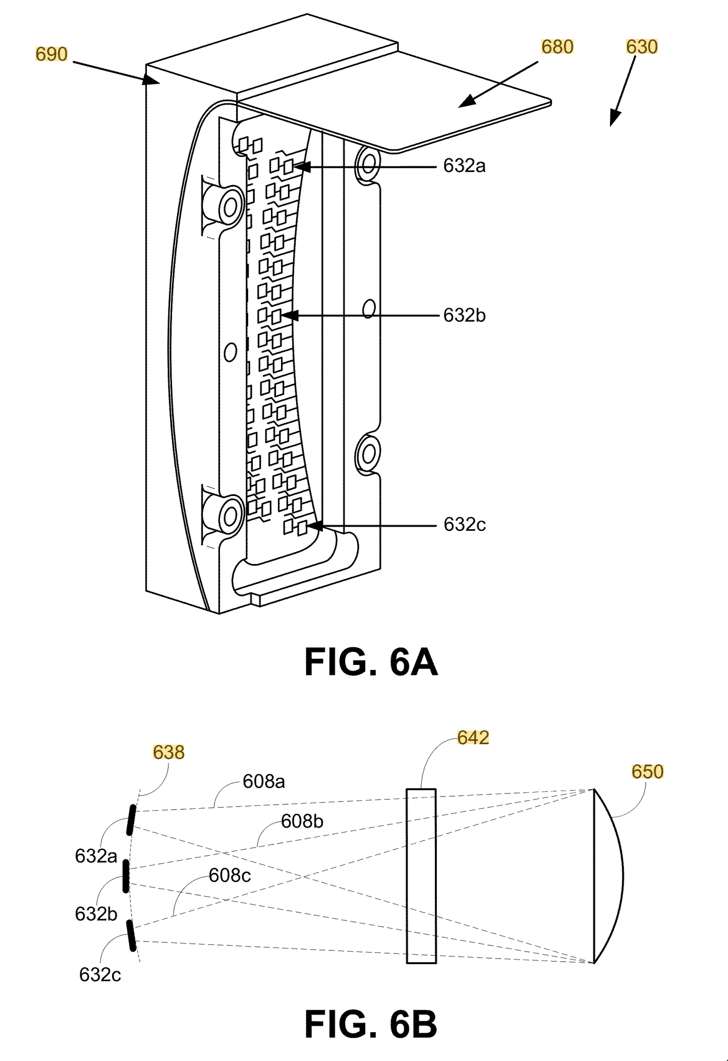
The reason for doing that is because, due to the simple design of the lens, it was necessary to arrange the lasers and detectors along a curved arc. Interestingly, a Google (now Waymo) patent US8836922B1 describes using a flexible substrate to achieve the curve.
Solid state arrays
Solid state arrays put lasers or detectors on a single chip. The obvious benefit is vastly simpler manufacturing and consistency. High performance edge-emitting laser diodes shoot lasers to the sides so you can’t just put a bunch of them in an array on a chip, so you’ll have to make do with lower power VCSELs.
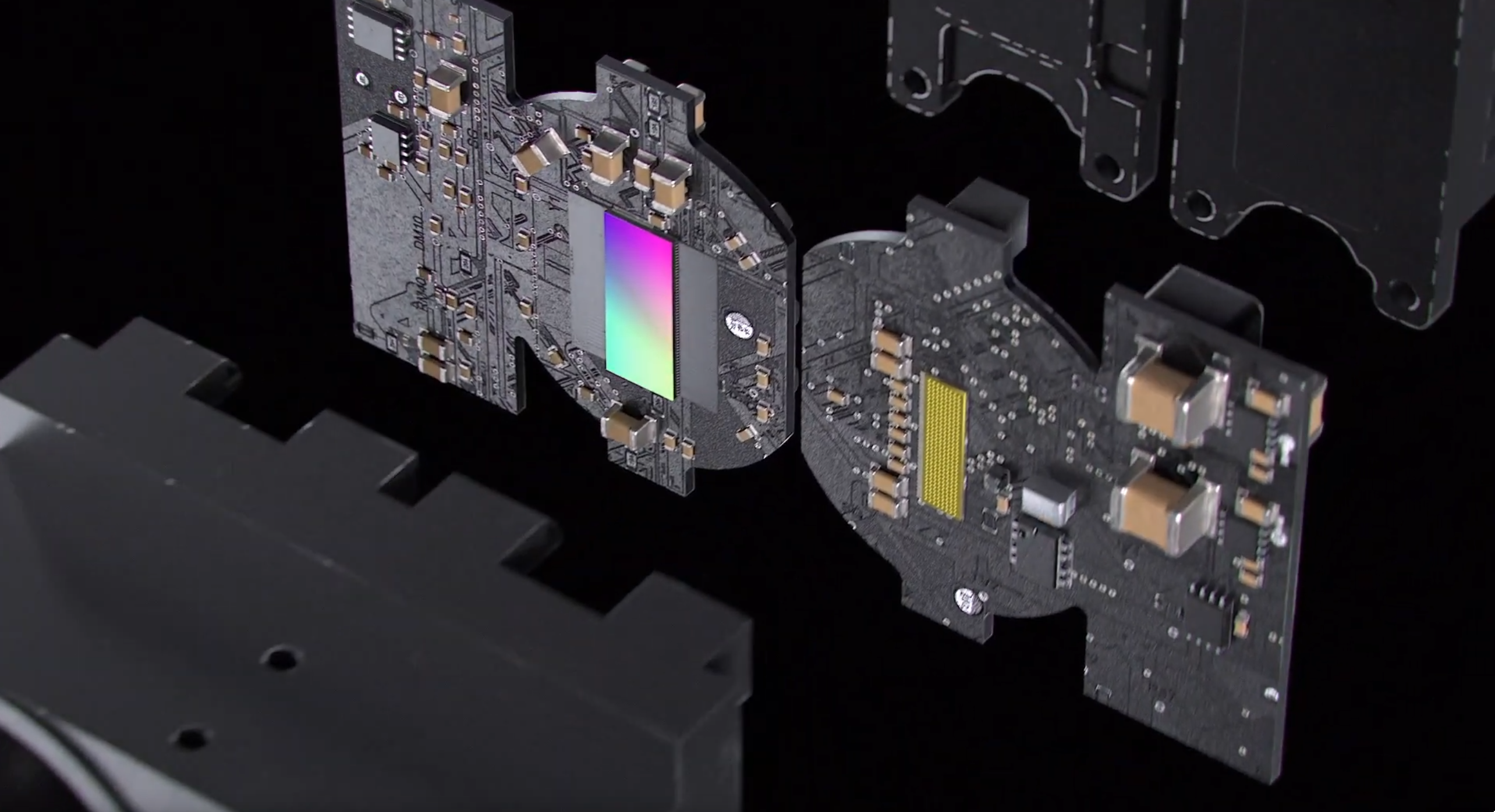
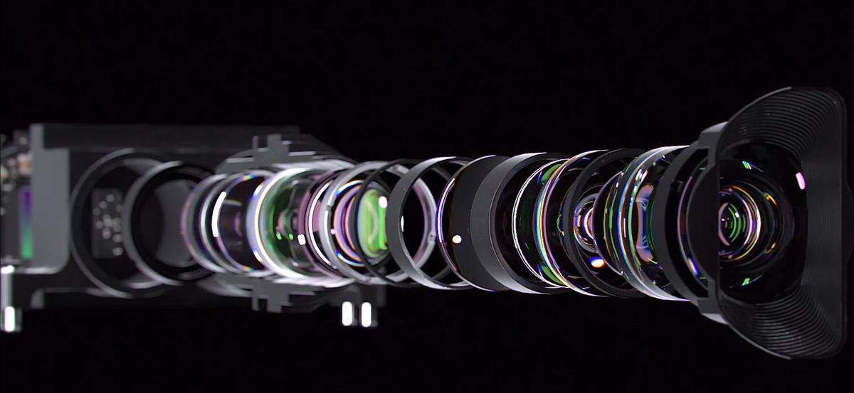
Since the laser array or detector array is now flat, the optical design will be somewhat more complex. You’ll need the lens to be image space telecentric since your flat array of lasers all produces parallel beams.
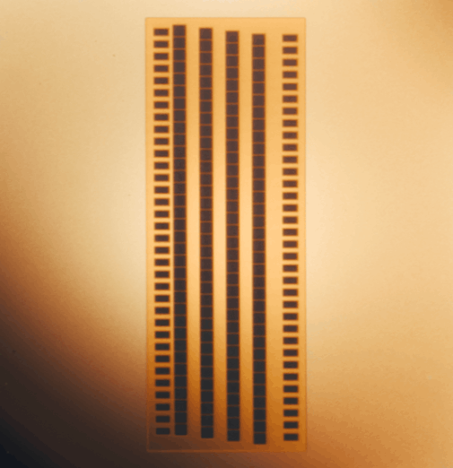
For lasers, only VCSELs are compatible with this method. As for detectors, SPADs are also vastly more amenable to solid state arrays, although APD arrays are also available (but with fewer elements). This is because, as discussed earlier, SPADs are compatible with typical chipmaking technologies and they output digital signals rather than analog ones, so you can fabricate them on a single chip, whereas APDs would typically require discrete components.
With large arrays, a lidar could sequentially fire small parts of an array instead of all of it at once. This is called electronically scanning. In effect, it is similar to scanning, except there are fixed elements already pointed in different directions rather than the same element being made to point in different directions. Electronically scanning has the advantage of less pixel crosstalk/blooming (more on this later) as well as being able to output more power per beam without running into thermal or safety limits.
Scanning and beam steering methods
Spinning
Perhaps the most straightforward way to do beam steering is to just spin the whole lidar, which gives you 1D angular discernment. The first advantage is that this gives you 360 degree field of view. This also has the advantage of being highly compatible with arrays, so you can have a vertical array while spinning horizontally. Spinning lidars have basically only one moving part.

An encoder is used to measure the angle of the turret.
The challenges of spinning are that:
- You need to send power and data between the spinning turret and the stationary base somehow. The earliest spinning multi-beam lidar, the Velodyne HDL-64E, used a mercury-wetted slip ring (Mercotac 305). This is very efficient, but expensive, fragile, and somewhat environmentally unfriendly. Later spinning lidars transmit power wirelessly through a transformer, and data wirelessly through an optical link.
- The cylindrical window can degrade optical performance. Some lidars have compensator optics to suppress aberrations from the cylindrical window. The Quanergy M8 had a variant with an octagonal window instead. Some lidars spin externally (such as the Waymo Laser Bear Honeycomb, Velodyne HDL-64E, and Velodyne HDL 32). But spinning externally makes it less robust against the environment.
- Thermal dissipation. The spinning turret houses most of the energy-intensive lasers but it has no direct contact with the outside except through the bearing.
- Despite having only one moving part, the spinning turret is a rather large and heavy part, and some early spinning lidars like Velodynes tended to fail a lot when the bearing was damaged or wore out. This is an especially big problem if the turret isn’t well-balanced.
Spinning mirror
Using a spinning polygonal mirror is one of the oldest and most reliable ways to scan a laser beam, which is again a 1D scanning method. This is used in, for example, laser printers.

As with spinning lidars, an encoder is used to measure the angle of the polygonal mirror.
Compared to spinning the whole turret, this has the main drawback of having a much narrower field of view (about 120 degrees is typical, as opposed to 360 degrees). However, it has the advantage of having a lighter moving part without having to deal with power transmission and heat dissipation and stuff.
Oscillating mirrors/galvos
This is a flat mirror that oscillates in angle to steer the beam, which can be either 1D or 2D.

Typically, a lightweight mirror is connected to a galvanometer in what’s called a mirror galvanometer (galvo). A galvanometer is one of the most basic ways to measure electrical current: it consists of a spring, a magnet, and a solenoid. When a current passes through the solenoid, it creates a magnetic field, which causes a torque to be applied as it tries to align itself with the magnet. The spring resists this force, so the amount it ends up turning is dependent on the current.
Nowadays, fast galvos are incredibly good and are used in all sorts of applications, like laser light shows, engraving, and so on.
Compared to spinning mirrors, this is somewhat less reliable, since reciprocating motion is typically less reliable than constant rotation.
Unlike spinning mirrors, you can have a single mirror that’s actuated in two axes (a 2D galvo) that allows you to steer your beam in both directions with a single mirror.
MEMS mirror
A MEMS (micro-electromechanical system) mirror is simply a mirror that is really small, typically an oscillating mirror. Because it is so small, it is typically considered “solid state” even if it is physically a moving part. Like macroscopic oscillating mirrors, MEMS scanner may be either 1D or 2D.
The primary advantage of MEMS is low cost and relatively better reliability. After all, the rate at which your moving part wears out is strongly dependent on the mass and moments of inertia of that moving part, so keeping it as light as possible makes it more resilient.
There are, however, a couple of drawbacks:
- The optical aperture may be limited by the tiny size of the mirror. With lasers, the bigger the aperture, the more it stays collimated (and hence the less it spreads out), so you want the aperture to be as large as possible usually.
- Cooling a tiny mirror may be hard. Your entire laser output is bouncing off a tiny surface with tiny thermal pathways. Hence, the mirror should be kept as reflective as possible.
Optical phased arrays
A phased array has many array elements whose phase is slightly offset. As the contributions from each element interfere, a beam is formed where they interfere constructively, and everywhere else, destructive interference causes it to cancel out.
Phased arrays are common in radar. However, the fundamental physical problem of phased arrays is that the element size must be close to the size of the wavelength, and the wavelength of light (about a micron) is way smaller than the wavelength of radio waves (ranging from millimeters to many meters). If your array spacing is too big, your beam would have very poor collimation and tons of side lobes.
You can use phased arrays for both the transmitter and receiver. For the receiver, you would have an array of optical antennae which are tiny nanophotonic detectors that can each measure the phase and amplitude.
So far, due to the physical challenges with phased arrays, there have been no commercial successes. The Quanergy S3 and an Israeli startup called Oryx Vision were two well-known entrants to attempt optical antennae.
Baraja SpectrumScan
This uses a frequency sweep laser with a fixed prism. Prisms have dispersion, which means that the index of refraction changes with wavelength (hence turning sunlight into a rainbow), so by changing the wavelength of the laser, the angle is changed. This allows it to scan in 1D. Baraja uses a MEMS mirror for the other axis.

This requires using a high quality fiber laser or tunable diodes that can do large frequency sweeps, which can be costly.
Risley prisms
A prism is a triangular piece of glass that can bend light. Risley prisms are a pair of two prisms that can rotate along the optical axis. When the prisms are lined up, they both bend light the same way, and the beam gets bent a lot. When they are opposite of each other, they cancel each other out, and the beam goes through straight without bending.

Basically, when you have two prisms, one with angle θ and one with angle ωθ, the x, y direction of the beam is proportional to:

Speed ratio between prisms: -0.743
The Livox lidars are notable for using Risley prisms. You can make other scan patterns by varying the speed of the prisms, and by putting an array of multiple lasers (e.g. the Livox Horizon’s 6 lasers) instead of one laser.
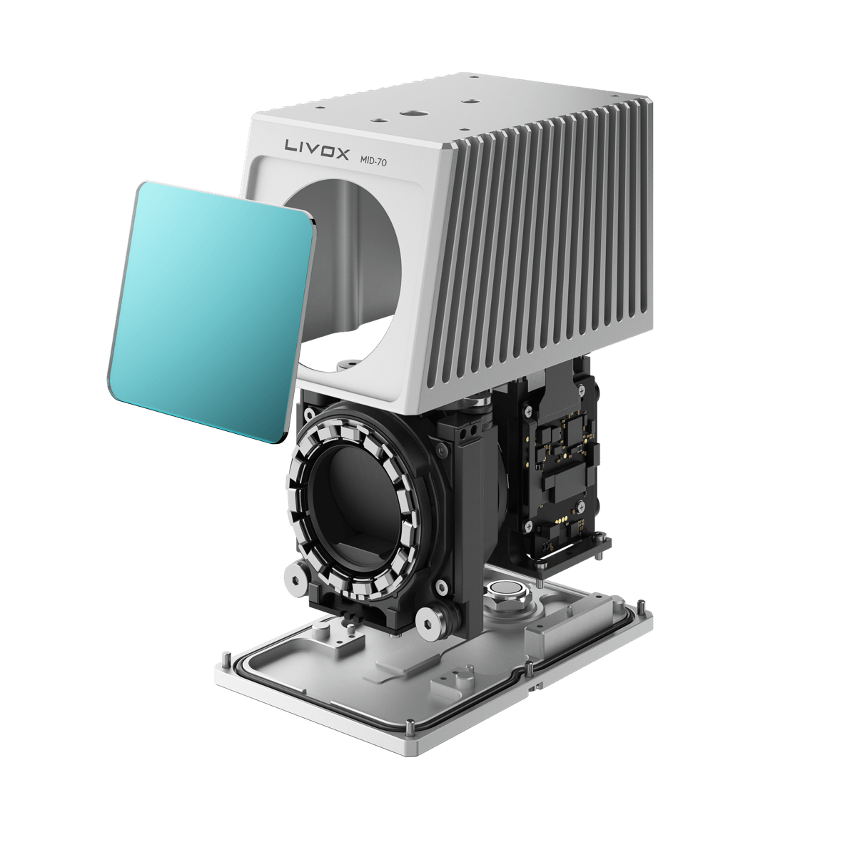
The advantage of Risley prisms is that, like polygonal mirrors, it’s cheap and robust to have things spinning at a constant speed. However, the disadvantage is very narrow field of view, and a weird scanning pattern. For some applications, the scan pattern can be an advantage, for example surveying applications where the lidar can be stationary for long periods of time, gradually covering a dense area.
Combining two 1D methods
Many lidars combine two 1D methods, e.g.:
- Horizontally spinning turret + vertical array (e.g. Velodyne pucks, Ouster OS series, Hesai Pandar)
- Horizontally spinning turret + vertically spinning polygonal mirror (e.g. Leica BLK360)
- Horizontal spinning mirror + vertical spinning or oscillating mirror (e.g. Luminar Iris, Seyond Falcon)
- Horizontal spinning mirror + array (e.g. Hesai AT512)